Main Content

gimbal

Add gimbal to satellite, platform, or ground station

Since R2021a

Description

example

gimbal(parent) adds a default Gimbal object to each parent in the parent vector, which can be a satellite, a platform, or a ground station. A gimbal can be added to satellites, platform, and ground stations, and dynamically change orientation independent of the parent. Transmitters, receivers, and conical sensors can be mounted on the gimbals.

gimbal(parent,Name=Value) adds gimbals to parents in parent using additional parameters specified by optional name-value pairs.

gim = gimbal(___) returns the added gimbals in the row vector gim.

Examples

expand all

Create a satellite scenario with a start time of 15-June-2021 8:55:00 AM UTC and a stop time of five days later. Set the simulation sample time to 60 seconds.

startTime = datetime(2021,6,21,8,55,0);
stopTime = startTime + days(5);
sampleTime = 60;                                      % seconds
sc = satelliteScenario(startTime,stopTime,sampleTime)
sc = 
  satelliteScenario with properties:

         StartTime: 21-Jun-2021 08:55:00
          StopTime: 26-Jun-2021 08:55:00
        SampleTime: 60
      AutoSimulate: 1
        Satellites: [1×0 matlabshared.satellitescenario.Satellite]
    GroundStations: [1×0 matlabshared.satellitescenario.GroundStation]
           Viewers: [0×0 matlabshared.satellitescenario.Viewer]
          AutoShow: 1

Add a satellite to the scenario using Keplerian orbital elements.

semiMajorAxis = 7878137;                                                                    % meters
eccentricity = 0;
inclination = 50;                                                                           % degrees
rightAscensionOfAscendingNode = 0;                                                          % degrees
argumentOfPeriapsis = 0;                                                                    % degrees
trueAnomaly = 50;                                                                           % degrees
sat = satellite(sc,semiMajorAxis,eccentricity,inclination,rightAscensionOfAscendingNode, ...
    argumentOfPeriapsis,trueAnomaly)
sat = 
  Satellite with properties:

               Name:  Satellite 1
                 ID:  1
     ConicalSensors:  [1x0 matlabshared.satellitescenario.ConicalSensor]
            Gimbals:  [1x0 matlabshared.satellitescenario.Gimbal]
       Transmitters:  [1x0 satcom.satellitescenario.Transmitter]
          Receivers:  [1x0 satcom.satellitescenario.Receiver]
           Accesses:  [1x0 matlabshared.satellitescenario.Access]
        GroundTrack:  [1x1 matlabshared.satellitescenario.GroundTrack]
              Orbit:  [1x1 matlabshared.satellitescenario.Orbit]
    OrbitPropagator:  sgp4
        MarkerColor:  [0.059 1 1]
         MarkerSize:  6
          ShowLabel:  true
     LabelFontColor:  [1 1 1]
      LabelFontSize:  15

Add a ground station, which represents the location to be photographed, to the scenario.

gs = groundStation(sc,Name="Location to Photograph", ...
    Latitude=42.3001,Longitude=-71.3504)                 % degrees
gs = 
  GroundStation with properties:

                 Name:  Location to Photograph
                   ID:  2
             Latitude:  42.3 degrees
            Longitude:  -71.35 degrees
             Altitude:  0 meters
    MinElevationAngle:  0 degrees
       ConicalSensors:  [1x0 matlabshared.satellitescenario.ConicalSensor]
              Gimbals:  [1x0 matlabshared.satellitescenario.Gimbal]
         Transmitters:  [1x0 satcom.satellitescenario.Transmitter]
            Receivers:  [1x0 satcom.satellitescenario.Receiver]
             Accesses:  [1x0 matlabshared.satellitescenario.Access]
          MarkerColor:  [1 0.4118 0.1608]
           MarkerSize:  6
            ShowLabel:  true
       LabelFontColor:  [1 1 1]
        LabelFontSize:  15

Add a gimbal to the satellite. You can steer this gimbal independently of the satellite.

g = gimbal(sat)
g = 
  Gimbal with properties:

                Name:  Gimbal 3
                  ID:  3
    MountingLocation:  [0; 0; 0] meters
      MountingAngles:  [0; 0; 0] degrees
      ConicalSensors:  [1x0 matlabshared.satellitescenario.ConicalSensor]
        Transmitters:  [1x0 satcom.satellitescenario.Transmitter]
           Receivers:  [1x0 satcom.satellitescenario.Receiver]

Track the location to be photographed using the gimbal.

pointAt(g,gs);

Add a conical sensor to the gimbal. This sensor represents the camera. Set the field of view to 60 degrees.

camSensor = conicalSensor(g,MaxViewAngle=60)
camSensor = 
  ConicalSensor with properties:

                Name:  Conical sensor 4
                  ID:  4
    MountingLocation:  [0; 0; 0] meters
      MountingAngles:  [0; 0; 0] degrees
        MaxViewAngle:  60 degrees
            Accesses:  [1x0 matlabshared.satellitescenario.Access]
         FieldOfView:  [0x0 matlabshared.satellitescenario.FieldOfView]

Add access analysis to the conical sensor between the camera and the location to be photographed.

ac = access(camSensor,gs)
ac = 
  Access with properties:

    Sequence:  [4 2]
    LineWidth:  3
    LineColor:  [0.3922 0.8314 0.0745]

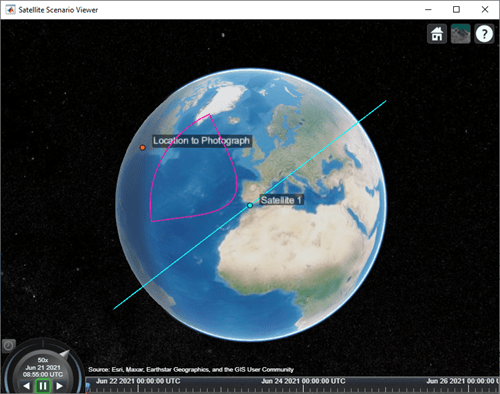
Visualize the field of view of the camera by using the Satellite Scenario Viewer.

v = satelliteScenarioViewer(sc);
fieldOfView(camSensor);

Determine the intervals during which the camera can see the geographical site.

t = accessIntervals(ac)
t=35×8 table
          Source                   Target             IntervalNumber         StartTime                EndTime           Duration    StartOrbit    EndOrbit
    __________________    ________________________    ______________    ____________________    ____________________    ________    __________    ________

    "Conical sensor 4"    "Location to Photograph"           1          21-Jun-2021 10:38:00    21-Jun-2021 10:55:00      1020           1            2   
    "Conical sensor 4"    "Location to Photograph"           2          21-Jun-2021 12:36:00    21-Jun-2021 12:58:00      1320           2            3   
    "Conical sensor 4"    "Location to Photograph"           3          21-Jun-2021 14:37:00    21-Jun-2021 15:01:00      1440           3            4   
    "Conical sensor 4"    "Location to Photograph"           4          21-Jun-2021 16:41:00    21-Jun-2021 17:04:00      1380           5            5   
    "Conical sensor 4"    "Location to Photograph"           5          21-Jun-2021 18:44:00    21-Jun-2021 19:07:00      1380           6            6   
    "Conical sensor 4"    "Location to Photograph"           6          21-Jun-2021 20:46:00    21-Jun-2021 21:08:00      1320           7            7   
    "Conical sensor 4"    "Location to Photograph"           7          21-Jun-2021 22:50:00    21-Jun-2021 23:04:00       840           8            8   
    "Conical sensor 4"    "Location to Photograph"           8          22-Jun-2021 09:51:00    22-Jun-2021 10:02:00       660          13           13   
    "Conical sensor 4"    "Location to Photograph"           9          22-Jun-2021 11:46:00    22-Jun-2021 12:07:00      1260          14           15   
    "Conical sensor 4"    "Location to Photograph"          10          22-Jun-2021 13:46:00    22-Jun-2021 14:10:00      1440          15           16   
    "Conical sensor 4"    "Location to Photograph"          11          22-Jun-2021 15:50:00    22-Jun-2021 16:13:00      1380          16           17   
    "Conical sensor 4"    "Location to Photograph"          12          22-Jun-2021 17:53:00    22-Jun-2021 18:16:00      1380          18           18   
    "Conical sensor 4"    "Location to Photograph"          13          22-Jun-2021 19:55:00    22-Jun-2021 20:18:00      1380          19           19   
    "Conical sensor 4"    "Location to Photograph"          14          22-Jun-2021 21:58:00    22-Jun-2021 22:16:00      1080          20           20   
    "Conical sensor 4"    "Location to Photograph"          15          23-Jun-2021 10:56:00    23-Jun-2021 11:16:00      1200          26           27   
    "Conical sensor 4"    "Location to Photograph"          16          23-Jun-2021 12:56:00    23-Jun-2021 13:19:00      1380          27           28   
      ⋮

Calculate the maximum revisit time in hours.

startTimes = t.StartTime;
endTimes = t.EndTime;
revisitTimes = hours(startTimes(2:end) - endTimes(1:end-1));
maxRevisitTime = max(revisitTimes)                             % hours
maxRevisitTime = 12.6667

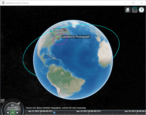
Visualize the revisit times that the camera photographs of the location.

play(sc);

Input Arguments

expand all

Element of scenario to which you add the gimbal, specified as a scalar or vector of satellites, platforms, or ground stations. The number of gimbals specified is determined by the size of the inputs.

  • If parent is a scalar, all gimbals are added to the parent.

  • If parent is a vector and the number of gimbals specified is one, that gimbal is added to each parent.

  • If parent is a vector and the number of gimbals specified is more than one, the number of gimbals must equal the number of parents and each parent gets one gimbal.

Name-Value Arguments

Specify optional pairs of arguments as Name1=Value1,...,NameN=ValueN, where Name is the argument name and Value is the corresponding value. Name-value arguments must appear after other arguments, but the order of the pairs does not matter.

Before R2021a, use commas to separate each name and value, and enclose Name in quotes.

Example: 'MountingAngle'=[20;35;10] sets the yaw, pitch, and roll angles of the gimbal to 20, 35, and 10 degrees, respectively.

Note

The size of the name-value arguments defines the number of gimbals that you can specify. To understand how to specify multiple gimbals, refer to these properties.

You can set this property only when calling the gimbal function. After you call the gimbal function, this property is read-only.

Gimbal name, specified as a name-value argument consisting of 'Name' and a string scalar, string vector, character vector, or a cell array of character vectors.

  • If you are adding only one gimbal, specify Name as a string scalar or a character vector.

  • If you are adding multiple gimbals, specify Name as a string scalar, character vector, string vector, or a cell array of character vectors. All gimbals that you add as a string scalar or a character vector are assigned the same specified name. The number of elements in the string vector or cell array of character vectors must equal the number of gimbals that you are adding. Each gimbal is assigned the corresponding name from the vector or cell array.

In the default value, idx is the ID assigned by the satellite scenario.

Data Types: char | string

Mounting location with respect to the parent object in meters, specified as a three-element vector or a matrix. The position vector is specified in the body frame of the input parent.

  • If you are adding one gimbal, MountingLocation is a three-element vector. The elements specify the x, y, and z components of the Cartesian coordinates in the body frame of gimbal.

  • If you are adding multiple gimbals, MountingLocation can be a three-element vector or a matrix. When specified as a vector, the same set of mounting locations are assigned to all specified gimbals. When specified as a matrix, MountingLocation must contain three rows and the same number of columns as the gimbals. The columns correspond to the mounting location of each specified gimbal and the rows correspond to the mounting location coordinates in the parent body frame.

When the AutoSimulate property of the satellite scenario is false, you can modify the MountingLocation property only when SimulationStatus is NotStarted. You can use the restart function to reset SimulationStatus to NotStarted, but doing so erases the simulation data.

Data Types: double

Mounting orientation with respect to parent object in degrees, specified as a three-element row vector of positive numbers. The elements of the vector correspond to yaw, pitch, and roll, in that order. Yaw, pitch, and roll are positive rotations about the z-axis, intermediate y-axis, and intermediate x-axis of the parent.

  • If you are adding one gimbal, the MountingAngles property is a three-element vector.

  • If you are adding multiple gimbals the MountingAngles property can be a three-element vector or a matrix. When specified as a vector, the same set of mounting angles are assigned to all specified gimbals. When specified as a matrix, MountingAngles must contain three rows and the same number of columns as the gimbals. The columns correspond to the mounting angles of each specified gimbal and the rows correspond to the yaw, pitch, and roll angles in the parent body frame.

When the AutoSimulate property of the satellite scenario is false, you can modify the MountingAngles property only when SimulationStatus is NotStarted. You can use the restart function to reset SimulationStatus to NotStarted, but doing so erases the simulation data.

Example: [0; 30; 60]

Data Types: double

Output Arguments

expand all

Gimbal object attached to parent, returned as either a scalar or a vector.

When the AutoSimulate property of the satellite scenario is false, you can call the gimbal function only when SimulationStatus is NotStarted. You can use the restart function to reset SimulationStatus to NotStarted, but doing so erases the simulation data.

Version History

Introduced in R2021a