Deploy ROS Node for Sign Following Robot with Time Synchronization Using Simulink
This example shows how to use Simulink® to generate a ROS stepping enabled node and control a simulated robot running on a separate ROS-based simulator.
In this example, you deploy a ROS node that implements a sign-following algorithm and controls the simulated robot to follow a path based on signs in the environment. The algorithm receives the location information and camera information from the simulated robot, which is running on a separate ROS-based simulator. The algorithm detects the color of the sign and sends the velocity commands to turn the robot based on the color. This example focuses on time source options for a ROS node generated from Simulink.
To see this example using Simulink or ROS2, see Sign-Following Robot with ROS in Simulink.
ROS Time Synchronization for Simulation
During Simulink simulation, you can control the simulation pace to iterate the model at a pace similar to the robot running on the ROS device using one of these options:
Gazebo Pacer Block - If the robot is running on Gazebo, use a Gazebo Pacer block to achieve time synchronization with Simulink. For an example, see Sign Following Robot with Time Synchronization Using ROS and Gazebo Co-Simulation (Robotics System Toolbox).
Simulation Pacing Options (Simulink) - Use Simulation Pacing to change the simulation pace to match with robot simulation time.
ROS Time Synchronization for Code Generation and Deployment
As for code generation and node deployment, the default time source is the system clock where the deployed node is running. The generated node is expected to run at a rate that you specified in Simulink. The rate may fluctuate based on the system specifications of the ROS device.
On the other hand, if there are more than one node in your project, you can use the time source from /clock topic to achieve time synchronization. For instructions to enable ROS time model stepping for deployment, see Enable ROS Time Model Stepping for Deployed ROS Nodes.
Create Clock Topic
If your simulator contains publisher to /clock topic, tune parameters and verify average rate for /clock topic. For example, you can modify real time update rate and max step size in Gazebo
Open a ROS terminal, and run the following command to verify the average rate for /clock topic:
$ rostopic hz /clock
If the simulator does not publish a /clock topic, consider the following alternatives:
Use a Digital Clock (Simulink) block as a time source in Simulink and run simulation to publish to
/clocktopic.Use a Current Time block as a time source in Simulink and deploy node to publish to
/clocktopic.Write a custom MATLAB® node or C++ node to publish to
/clocktopic.
You can use rosClockSimulator model to publish a /clock topic during simulation. You can adjust the Sample time of Digital Clock block to change the publishing rate of /clock topic.
open_system('rosClockSimulator.slx');
In order to maintain the simulation rate you specified in simulink before deployment, /clock topic must be updated consistently and at least twice faster than simulation rate. Otherwise, you may experience warning or termination during run time.
This example shows you how to enable ROS time model stepping and generate node to control robot for sign following.
Connect to a Robot Simulator
Start a ROS-based simulator for a differential-drive robot and configure MATLAB connection with the robot simulator.
To follow along with this example, download a virtual machine using instructions in Get Started with Gazebo and Simulated TurtleBot.
Start the Ubuntu® virtual machine desktop.
In the Ubuntu desktop, click the Gazebo Sign Follower ROS icon to start the Gazebo world built for this example.
Open Model and Configure Simulink
Setup the Simulink ROS preferences to communicate with the robot simulator.
Open the example model.
open_system('signFollowingRobotROS.slx');To configure the network settings for ROS.
From Simulation tab, Prepare group, select ROS Network.
Specify the IP address and port number of the ROS master in Gazebo. For this example, the ROS master in Gazebo is
192.168.243.158:11311. Enter192.168.243.158in the Hostname/IP address box and11311in the Port Number box.Click OK to apply changes and close the dialog box.
On each time step, the algorithm detects a sign from the camera feed, decides on turn and drives it forward. The sign detection is done in the Image Processing subsystem of the model.
open_system('signFollowingRobotROS/Image Processing');The Sign Tracking Logic subsystem implements a Stateflow® chart that takes in the detected image size and coordinates from Image Processing and provides linear and angular velocity to drive the robot.
open_system('signFollowingRobotROS/Sign Tracking Logic');Enable ROS Time Model Stepping
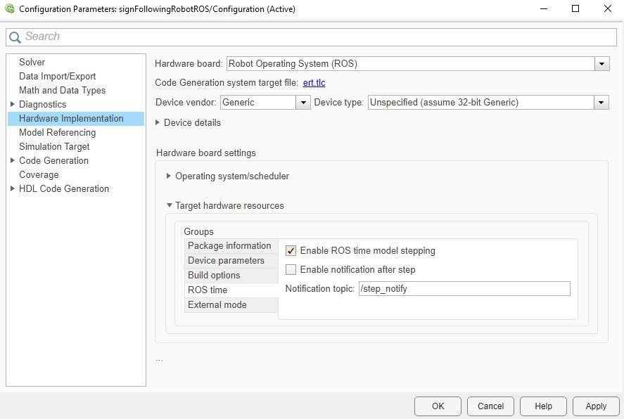
In the Prepare section under ROS tab, click Hardware Settings to open the model configuration parameters dialog box. Under Hardware Implementation > Hardware board settings > Target Hardware resources > ROS time, select Enable ROS time model stepping. Click OK to apply changes and close the dialog box.
(Optional) You can also select Enable notification after step check box if you wish to get a message every time ROS time is published. See more information in Enable ROS Time Model Stepping for Deployed ROS Nodes.
Deploy and Run Node from the Model
In the Connect section under ROS tab, make sure Deploy to is set to Remote Device. Click on Test Connection to verify that Simulink is able to connect with the remove device. In the Deploy section under ROS tab, click Build & Run to build, deploy, and start the program on remote device.
Once the deployed program starts running, the robot in the simulator will follow the sign and turn based on the color.
