Design Position Controlled Manipulator Using Simscape
This example shows you how to use Simulink® with Robotics System Toolbox™ to design a position controller for a manipulator and compute joint position required to drive the Simscape™ Multibody™ model of the manipulator.
Robotics System Toolbox, Simscape Multibody, and Robotics System Toolbox Robot Library Data support package are required to run this example.
Introduction
In this example, you will load an included robot model using loadrobot as a rigidBodyTree object, then create a Simscape Multibody model of the robot using smimport. Configure the model to accept joint torque and return the computed joint position and velocity. Implement a computed torque controller with joint position and velocity feedback using manipulator algorithm blocks. The controller receives joint position and velocity information from the robot model and sends torque commands to drive the robot to the desired joint position computed using Inverse Kinematics (IK).
Load Robot Model in Workspace
This example uses a model of the KINOVA® Gen3, a 7 degree-of-freedom robot manipulator. Call loadrobot to generate a rigidBodyTree model of the robot. Set the DataFormat properties to be consistent with Simscape.
robot = loadrobot("kinovaGen3",DataFormat="column");
Generate Simscape Multibody Model from Rigid Body Tree
Import the robot object into Simscape Multibody and get the model parameters.
robotSM = smimport(robot,ModelName="ManipulatorPositionControl_Subsystem");
model = get_param(robotSM,"Name");

Configure Simscape Multibody Model
Prepare the Simscape Multibody model to accept the joint torque inputs and return the joint positions and velocities. You can follow the steps below to manually configure the model or use the helperInstrumentSMModels helper function to automatically configure the model.
Manual Configuration of Simscape Multibody Model
In your model, double-click a Joint block. The Property Inspector dialog box opens.
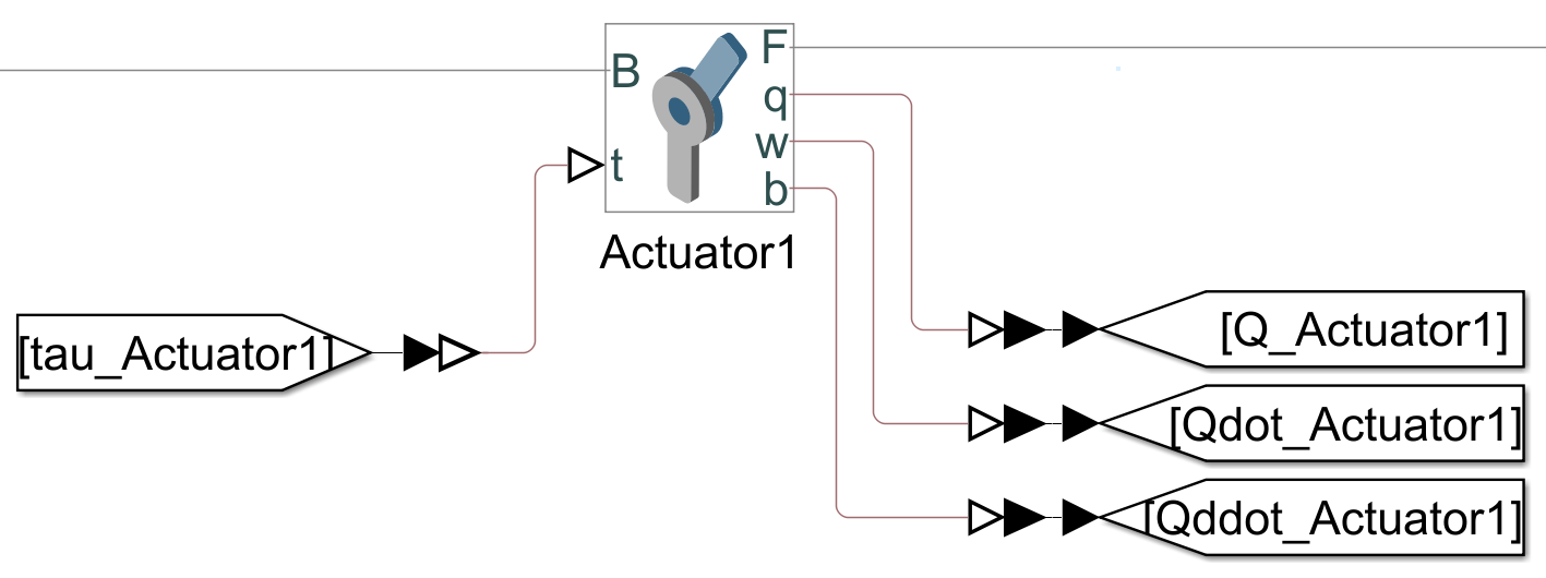
In the Property Inspector dialog box, select Z Revolute Primitive (Rz) > Actuation > Torque > Provided by Input, and select Z Revolute Primitive (Rz) > Actuation > Motion > Automatically computed. The block exposes a physical signal input port, labeled
t.

3. Select Z Revolute Primitive (Rz) > Sensing and enable Position, Velocity, and Acceleration. The block exposes a physical signal output ports, labeled q, w, and b.

4. Add a Simulink-PS Converter block from the Simscape > Utilities library, connect the Simulink-PS Converter block to physical signal input port t of the Joint block.
5. Add a From block from the Simulink > Signal Routing library to the input port of the Simulink-PS Converter block.
6. Add three PS-Simulink Converter blocks from the Simscape > Utilities library, connect the PS-Simulink Converter blocks to physical signal output ports q, w, and b of the Joint block.
7. Add three Goto blocks from the Simulink > Signal Routing library to the output port of the PS-Simulink Converter blocks.
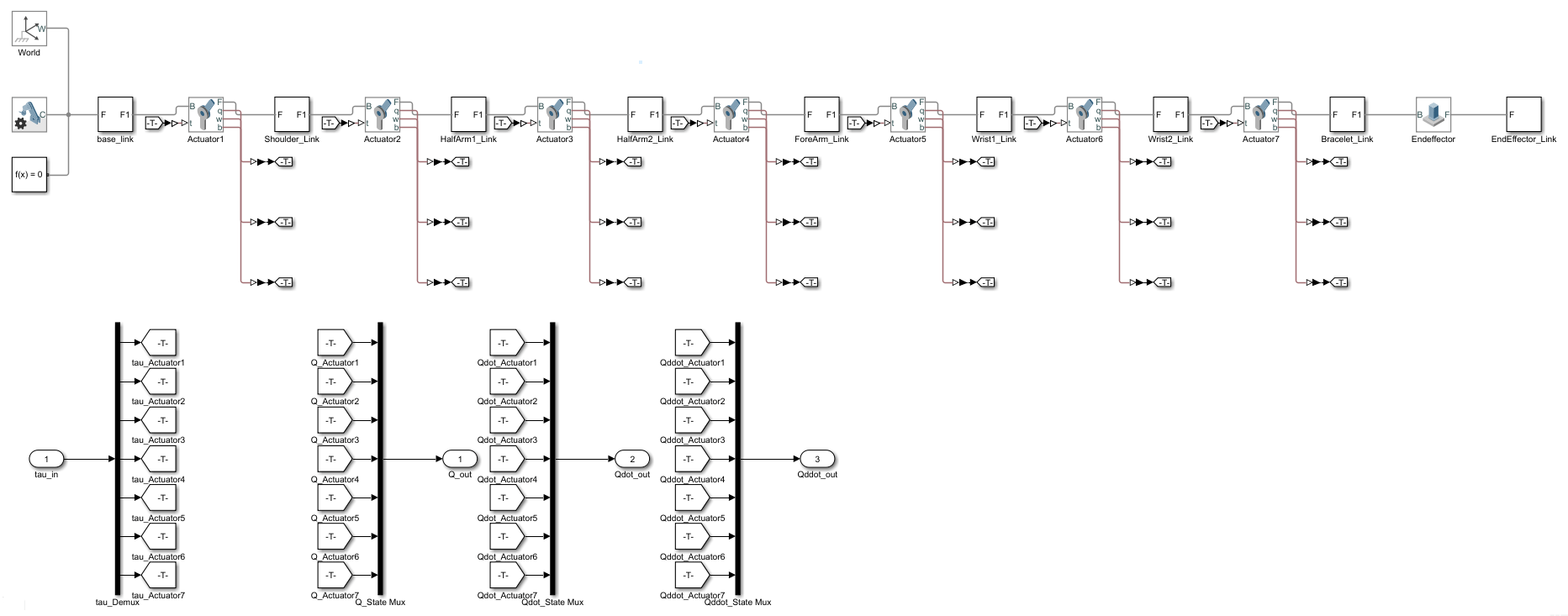
8. Repeat these steps for all the Joint blocks.
9. Add a Demux block from the Simulink > Signal Routing library and connect the joint torque Goto blocks related to the respective joint torque From blocks.
10. Add three Mux blocks from the Simulink > Signal Routing library and connect the joint motions From blocks related to the respective joint motions Goto blocks.
11. Create a subsystem of the Simscape Multibody model.
Configure Simscape Multibody Model Using Helper Function
Use the helperInstrumentSMModels helper function to automatically configure the model.
Call the helper function to automatically configure the Simscape Multibody model to accept torque input.
helperInstrumentSMModels.instrumentRBTSupportedJointInputs(model,robot,"torque")Call the helper function again to configure the Simscape Multibody model to enable position, velocity, and acceleration sensing at each joint.
helperInstrumentSMModels.instrumentRBTSupportedJointOutputs(model,robot,"motion")Create a subsystem of the Simscape Multibody model.
helperInstrumentSMModels.convertToSubsystem(model)
Set Up Variables in Model Workspace
Set up the variables in the model workspace that specify the start and end waypoints, and the joint starting position and velocity.
mdlWks = get_param(robotSM,"ModelWorkspace");
assignin(mdlWks,"robotToTest",robot)
assignin(mdlWks,"q0",robot.homeConfiguration)
assignin(mdlWks,"dq0",zeros(size(robot.homeConfiguration)))
Computed Torque Controller
The Computed Torque Controller subsystem is built using three robotics manipulator blocks: Joint Space Mass Matrix, Velocity Product Torque, and Gravity Torque. The rigidBodyTree model, robotToTest, is assigned in all those blocks.
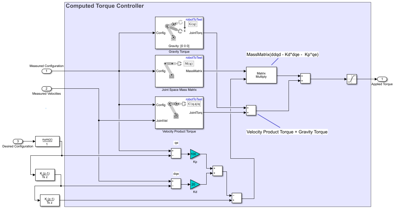
The Computed Torque Controller subsystem accepts Measured Configuration, Measured Velocities and Desired Configuration and returns Applied Torque for each joint of the manipulator.
For more details about this controller, see Perform Safe Trajectory Tracking Control Using Robotics Manipulator Blocks.
Set Up Controller Input
Add a Coordinate Transformation Conversion block from the Robotics System Toolbox > Utilities library to the model. Set the input representation as Translation Vector and the output representation as Homogeneous Transformation.

2. Add a Constant block and set the value as [0.5 0.5 0.5]. Connect the Constant block to the input port of the Coordinate Transformation Conversion block.
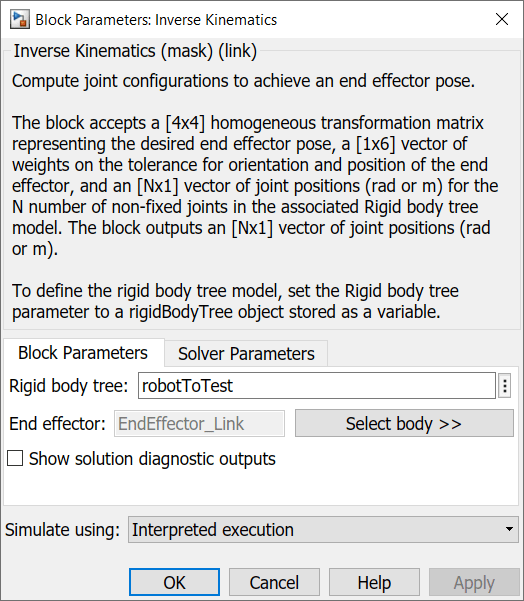
3. Add a Inverse Kinematics block from the Robotics System Toolbox > Manipulator Algorithms library to the model.
4. In the Inverse Kinematics block, specify the Rigid body tree model as robotToTest, then click Select body next to the End effector to select the end effector body.
5. Connect the output port of Coordinate Transformation Conversion block to the Pose port of the Inverse Kinematics block.
6. Add another Constant block and set the value as [0 0 0 1 1 1]. Connect the Constant block to the Weights port of the Inverse Kinematics block.
7. Connect a Delay block to the Config port of the Inverse Kinematics block and specify the Initial condition as q0.

8. Connect the output of the Delay block to the InitialGuess port of the Inverse Kinematics block.
Final Setup
Connect the Simscape Multibody Model subsystem, Computed Torque Controller subsystem, Controller Input blocks, and a Scope block as shown in figure.

Simulate Model
Open the provided ManipulatorPositionControl.slx model and replace the Robot subsystem with the subsystem created in ManipulatorPositionControl_Subsystem model above, for it to be able to fetch the meshes correctly.
open_system("ManipulatorPositionControl.slx")
Save the model and simulate it.
sim("ManipulatorPositionControl.slx","StopTime","5")
Visualize the multibody model in the Multibody Explorer.

Visualize the joint positions in the Scope.
