Road Plan Tool
Create and lay out roads
Description
The Road Plan Tool is the primary tool for creating and laying out roads. It allows for creation and manipulation of the 2D reference curve that the road layout is based on. The height of the road can be manipulated independently using the Road Height Tool. By default, the Road Plan Tool automatically creates intersections at locations where roads overlap. For information on how to avoid creating automatic junctions, see Prevent Creation of Automatic Junctions Between Roads.
Roads automatically participate in the terrain surface graph. For more information about this interaction, refer to the How Surfaces Work in RoadRunner.
Open the Road Plan Tool
On the RoadRunner toolbar, click the Road Plan Tool button:
![]()
Examples
Create a New Road
Click the Road Plan Tool button.
If another road is already selected, click away from any road to unselect it.
Optionally, click the desired road style in the Assets Browser to build a road of a particular style. If no road style is picked, a basic default style will be used. For more information about road styles, see Road Style Assets.
Right-click at the location you want to start a new road.
Right-click additional times to create additional road control points to extend and shape the road.
Move Road Control Point
Click the Road Plan Tool button.
Click the road you want to edit. The road is highlighted, and the control points are displayed and connected by light blue lines.
Click and drag the desired control point to move it.
Optionally, you can click to select the point, and then type a precise position in the Attributes pane.
Note
The end control points and the first interior control points have some special properties when roads are connected end-to-end:
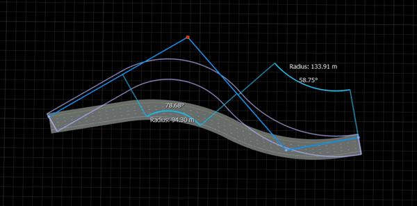
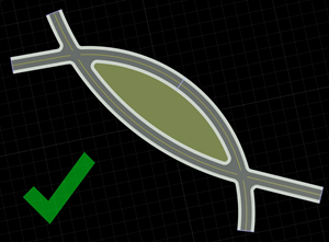
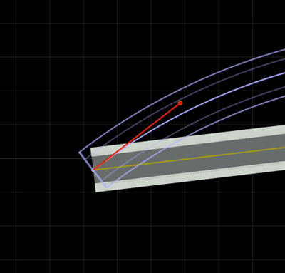
Moving the end control point of one of the roads will move the end of the connected road and update the first interior control point of the other road to ensure that the road directions remain aligned at this end, as shown here:
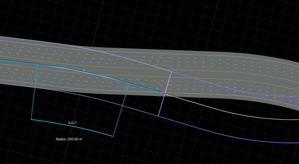
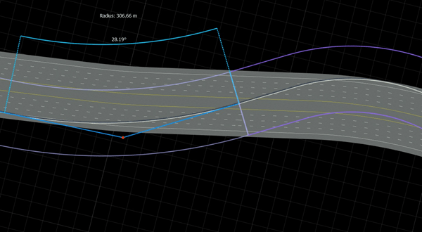
Moving the first interior control point of one of the roads will move the first interior control point of the other road (by rotating it about the end point) to ensure that the road directions remain aligned at this end, as shown here:
Insert New Control Point Within Existing Road
Click the Road Plan Tool button.
Click the road you want to edit.
Move the mouse cursor over the blue control line at the location you want to insert a node.
Right-click to insert a new node within the control line of the road.
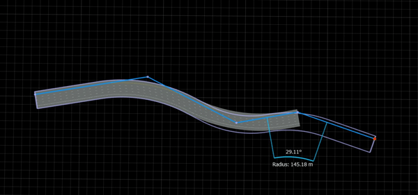
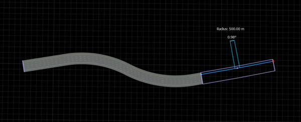
Adjust Radius of Road Curve
By default, the circular arcs in the road curves will fit in the space available. If a smaller curve radius is desired:
Click the Road Plan Tool button.
Click the road you want to edit. The road is highlighted, and the control points are displayed and connected by light blue lines.
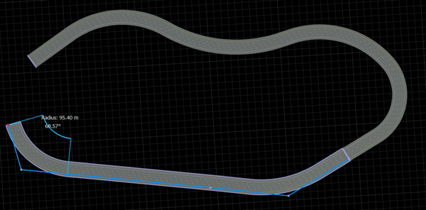
Click the control point closest to the circular arc you want to modify. The attributes of the selected control point will appear in the Attributes pane.
Adjust the Max Radius value to the desired radius. If you do not see anything change, then try a lower value, because Max Radius will limit the maximum radius of the arc.

Adjust Curvature of Road Curve
See Explicit Road Curves.
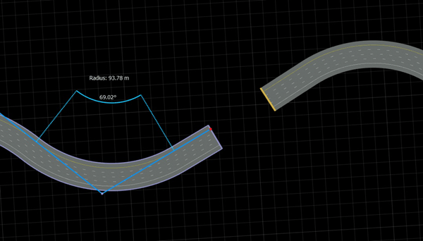
Shift Single Road Using Control Line
You can shift a single road on the editing canvas using a control line.
Click the Road Plan Tool button.
Click the road you want to shift. The road is highlighted, and the control points are displayed and connected by light blue control lines.
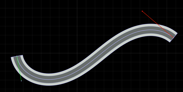
To shift the entire road, drag one of the control lines. While dragging the light blue line, the canvas displays a preview of the shifted road as a red outline. Note that the road mesh does not move until you release the control line.
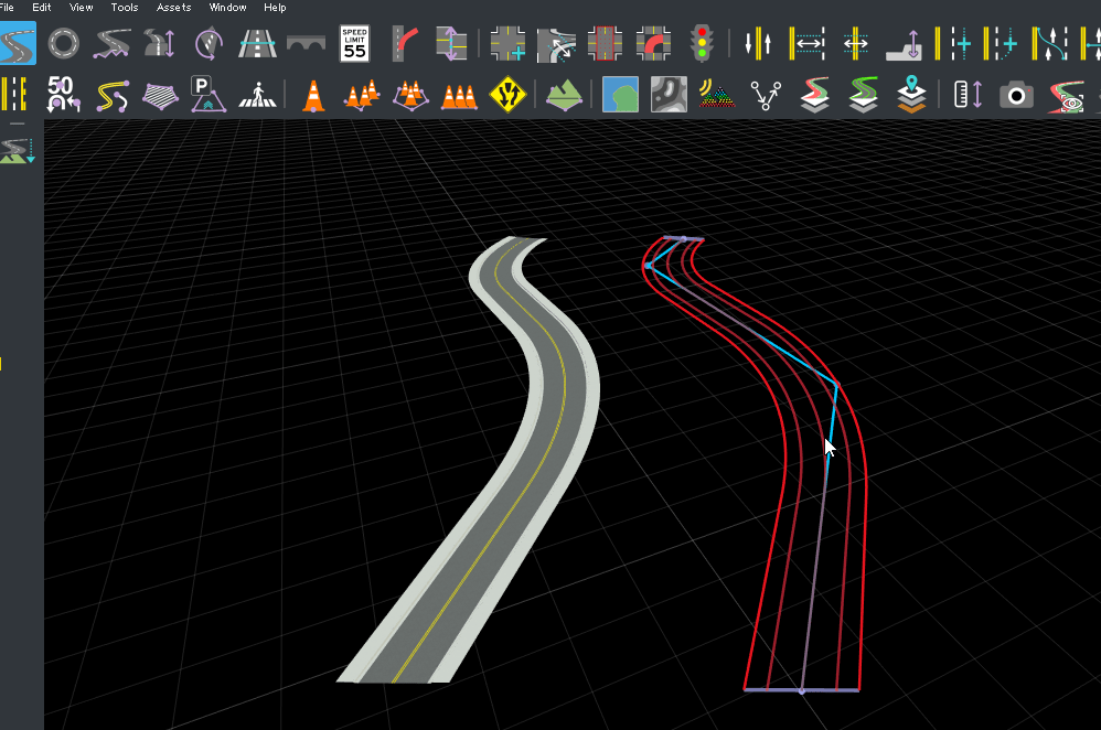
When you are satisfied with the road location indicated by the preview, release the control line. The road mesh shifts from the source location to the destination location.
Shift Multiple Roads Using Control Point
You can shift multiple roads on the editing canvas at the same time using control points.
Click the Road Plan Tool button.
Click and drag from the left side of the canvas to select multiple roads you want to move. The roads are highlighted, and the control points are displayed and connected by light blue control lines.
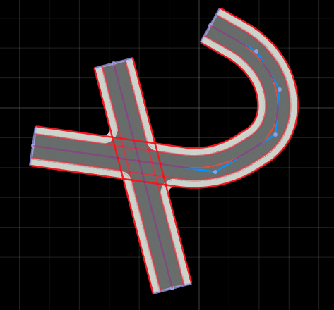
Click and drag from the right side of the canvas to select the same roads again. The control lines and control points turn red.
Click on a control point and drag it to a new location. While dragging the control point, the canvas displays a preview of the shifted roads as a red outline. Note that the road meshes do not move until you release the control point.
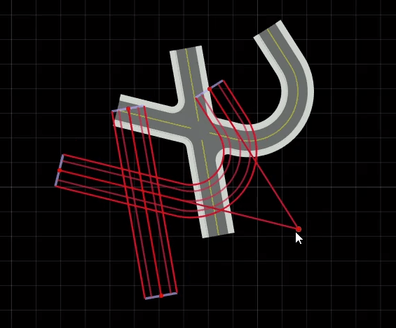
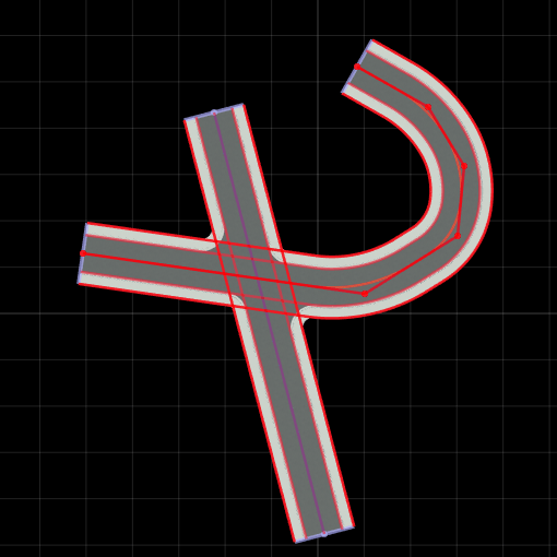
When you are satisfied with the new location of the roads indicated by the preview, release the control point. The road meshes shift from the source location to the destination location.
Extend Existing Road
You can extend an existing road in either direction by adding more control points, as follows:
Click the Road Plan Tool button.
Click the road you want to extend. The road is highlighted, and the control points are displayed and connected by light blue lines.
Click the control point on the end of the road you want to extend.
Right-click to create a new control point and extend the road.
Note
For optimal performance, avoid very long individual roads. Keeping individual roads under 500 m is recommended. To create stretches of road longer than 500 m, use multiple roads connected end-to-end. Refer to Create New Road Connected End-to-End with Another Road and Connect Two Roads End-to-End.
Create New Road Connected End-to-End with Another Road
In a similar fashion to extending an existing road, you can also create a new road that connects end-to-end with an existing road. The visual result is similar to extending the existing road, but there are some important situations where end-to-end roads are needed:
To avoid extremely long roads for performance reasons
To create a road loop or self-intersecting road
You can create an end-to-end road that connects with an existing road as follows:
Click the Road Plan Tool button.
If another road is already selected, click away from any road to unselect it.
Click the lavender road node line at the end of a road.
Right-click to create a new control point, which creates a new road that extends off the existing one.
Connect Two Roads End-to-End
Similar to the steps above, you can extend a road and simultaneously connect it to the end of an existing road as follows:
Click the Road Plan Tool.
Click the road you want to extend. The road is highlighted, and the control points are displayed and connected by light blue lines.
Click the control point on the end of the road you want to extend.
Right-click the lavender line at the end of another road.
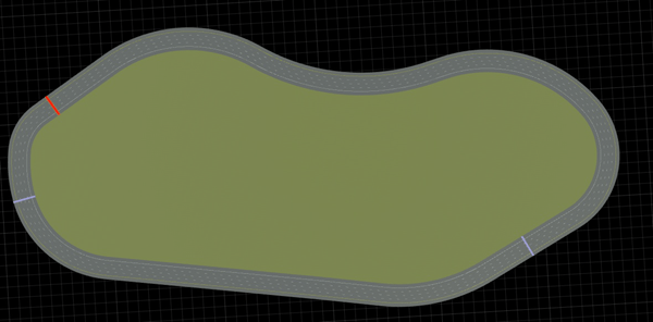
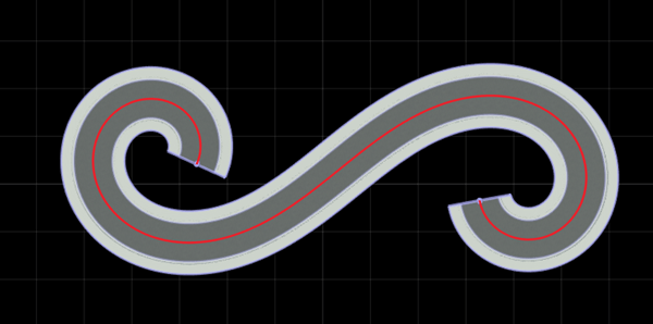
Create Road Loop
You can create a closed loop road by combining the steps above or by using the Road Circle Tool.
Note
Closed loops require at least three separate roads. You cannot form a loop from a single road.
Create the first road by using the Create a New Road steps.

Create the second road by using the Create New Road Connected End-to-End with Another Road steps.
Create the final road by using the Create New Road Connected End-to-End with Another Road steps, followed by the Connect Two Roads End-to-End steps to end the road.
Delete Road Control Point
Click the Road Plan Tool button.
Click the road you want to delete the point from. The road is highlighted, and the control points are displayed and connected by light blue lines.
Click the control point you want to delete.
Press the Delete key, or select Edit > Delete from the menu bar.
Delete Road
Click the Road Plan Tool button.
Click the road you want to delete.
Press the Delete key, or select Edit > Delete from the menu bar.
Create Intersection
At-grade intersections are created automatically in RoadRunner wherever two or more roads cross.
To create a four-way intersection, create two roads that fully overlap:
To create a T-junction, create two roads where one ends within the extents of the other:
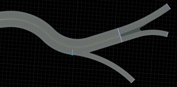
To create onramps, offramps, and road splits, refer to the Slip Road Tool documentation.
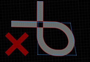
A single road should not overlap itself. If you need to create a road that loops back on itself, either chop the road with the Road Chop Tool, or create roads connected end-to-end:
Roads may not cross themselves |
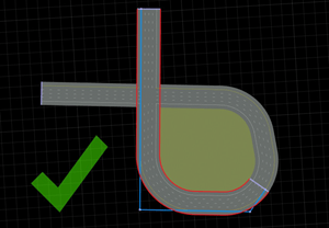
Instead, create two or more roads connected end-to-end |
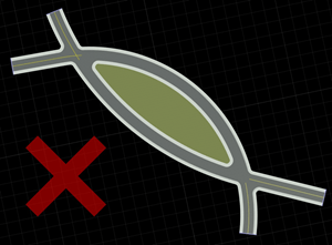
You might observe issues with lane markings when two roads cross each other twice (that is, two at-grade intersections are formed between the same two roads).
Avoid double-crossing roads. If you need to create a double-crossing situation, either chop one of the roads with the Road Chop Tool, or initially create one of the roads using two end-to-end roads.
Avoid roads that cross each other twice. |
Instead, split one of the roads in two (Note the lavender bar indicating an end-to-end connection.) |
Note
Intersections are only created when the roads have similar heights at the crossing locations. To adjust road heights, use the Road Height Tool.
Prevent Creation of Automatic Junctions Between Roads
RoadRunner automatically creates intersections wherever two or more roads cross. To prevent RoadRunner from creating automatic junctions between roads, use the Stack Level or Overlap Group attribute.
Stack Level
Two roads only produce an automatic junction if their Stack Level values are the same. For example, when creating an overpass in a highway interchange, you can define the levels of the overpass by assigning each level a different Stack Level value. If you also assign a road an Overlap Group value, then the road only creates automatic junctions with overlapping roads with the same Stack Level value and different Overlap Group values.
To modify the Stack Level value for a road, follow these steps:
Click the Road Plan Tool button.
Click the road for which you want to modify the Stack Level value.
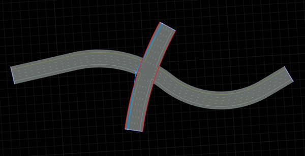
In the Attributes pane, under Road, increase or decrease the Stack Level value as desired to suit your scene. For example, in the figure, a straight road and a curved road overlap. However, because the Stack Level value for the straight road is set to
1and the Stack Level value for the curved road is set to0, these two roads do not automatically produce a junction.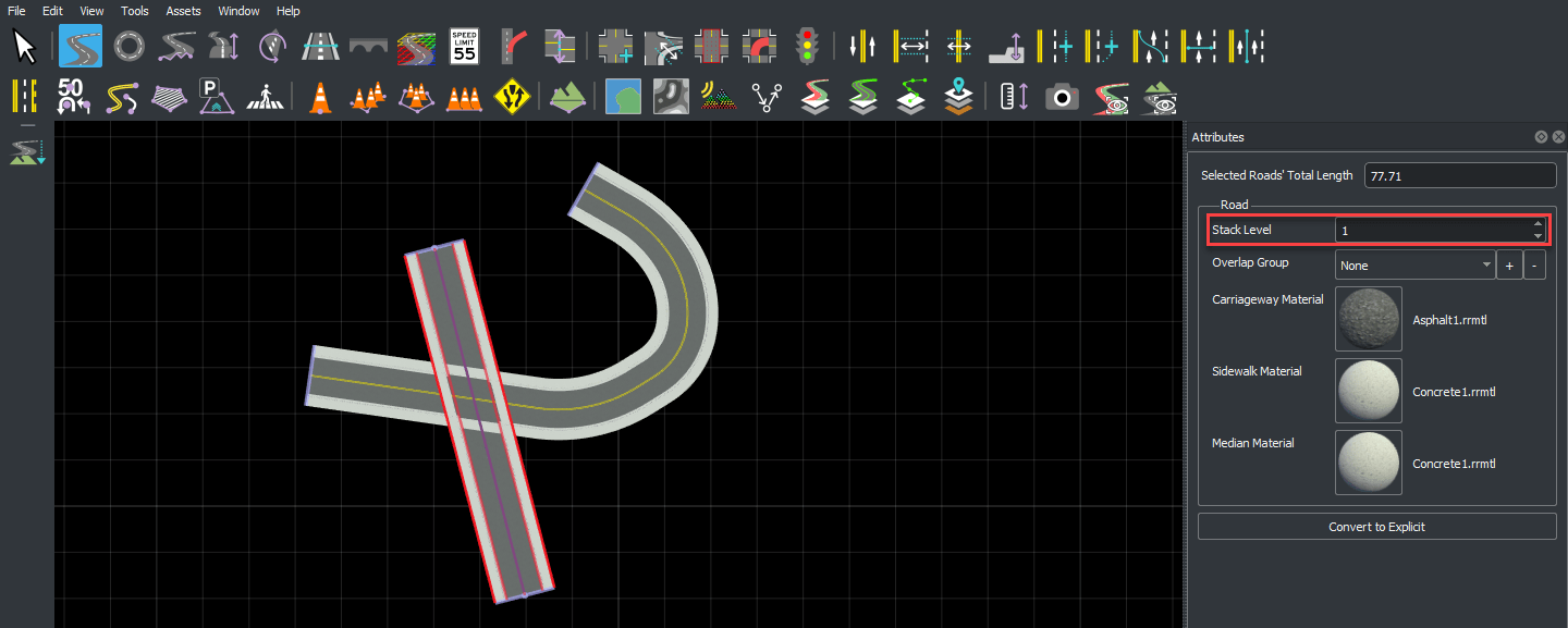

Overlap Group
Roads with the same Overlap Group value do not produce automatic junctions, even if they have the same Stack Level value. You can use the Overlap Group attribute when importing data where the junctions have already been defined (such as from ASAM OpenDRIVE®) to ensure that RoadRunner does not produce additional automatic junctions.
To modify the Overlap Group values for roads, follow these steps:
Click the Road Plan Tool button.
Click the road for which you want to assign an Overlap Group value.
In the Attributes pane, under Road, click the + button next to Overlap Group. This opens the Create Overlap Group dialog box. Enter the name of a group to assign the road to that overlap group.
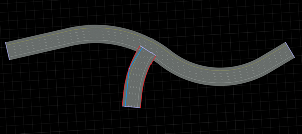
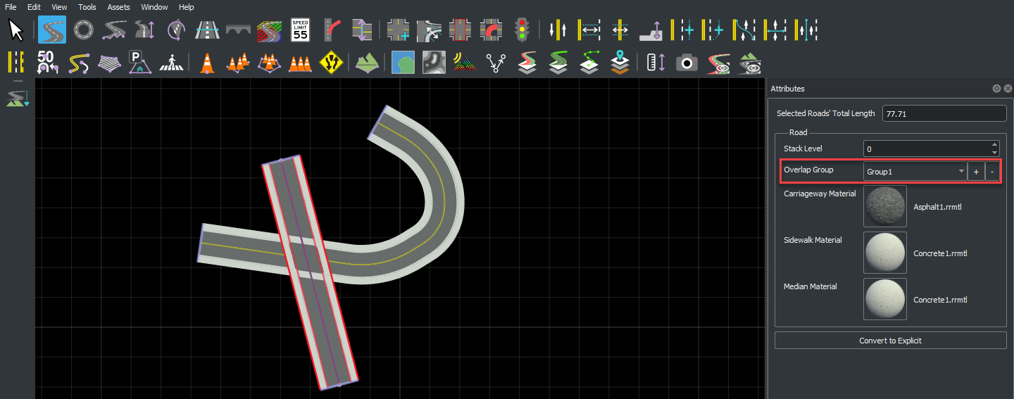
Repeat this step to assign the remaining roads to overlap groups. The roads assigned to the same overlap group do not produce an automatic junction. For example, in this figure, a curved road and a straight road overlap. Because the curved road and the straight road both have an Overlap Group
Group1, these two roads do not produce a junction.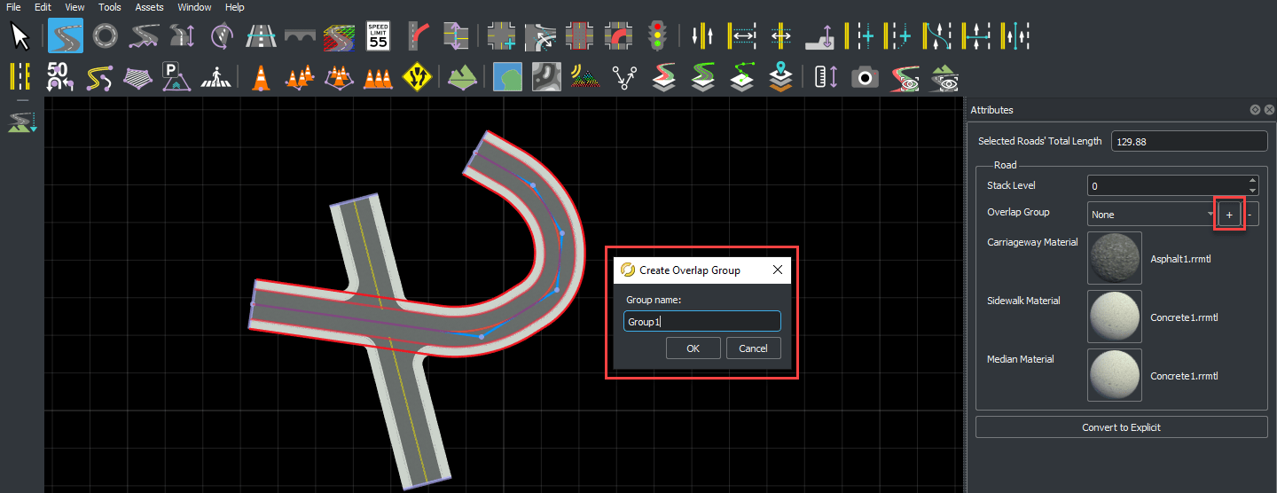
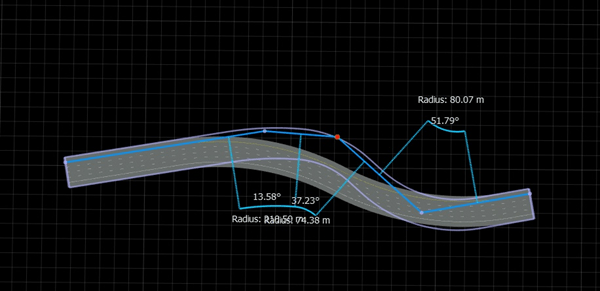
Explicit Road Curves
By default, new roads will be created out of straight lines and circular arcs. Roads created in this method are called "Automatic". It is sometimes desirable to instead define a road curve as an explicit set of straight lines, circular arcs, clothoids (spirals), and parametric cubics (Hermite curves).
Roads created in this method are called "Explicit." Each straight line, circular arc, clothoid (spiral), or parametric cubic (Hermite curve) is called a "Segment." The explicit road curve also allows you to set the tangents of the road at each control point. Editing the control points of an explicit curve is done the same as with an automatic curve.
Explicit curves can be used to create a road with a very specific profile (for example, a 50 m linear section, followed by a 20 m spiral with specific starting and ending curvatures, followed by a 30 m arc with specific curvature, and so on).
To build such a road, follow these steps:
Click the Road Plan Tool button.
Create a new road using these steps: Create a New Road.
Convert the new road to explicit form using these steps: Make Road Curve Explicit.
Adjust the type and properties of the first road section.
For each new section you want to add to the road:
Add a new section using these steps: Extend Existing Road.
Adjust the type and properties of the new road section.
Make Road Curve Explicit
Click the Road Plan Tool button.
Click the road you want to change.
In the Attributes pane, press Convert to Explicit.
Make Road Curve Automatic
Click the Road Plan Tool button.
Click the road you want to change.
In the Attributes pane, press Convert to Automatic.
Note
Converting an explicit curve to an automatic curve can slightly change the curve and insert additional points.
Change Tangent of Explicit Curve
Click the Road Plan Tool button.
Click the road you want to change.
Click and drag one of the tangent control points and move it to set the desired tangent.
Note
Setting tangents on a road may change the type of the segments connected to the affected control point.
Change Type of Segment
Click the Road Plan Tool button.
Click the road you want to change.
Click the segment you want to change.
In the Attributes pane, select the Type of the segment. This will automatically constrain the segment's points and tangents to match the type.
Change Length of Segment
Click the Road Plan Tool button.
Click the road you want to change.
Click the segment you want to change.
In the Attributes pane, adjust the Length of the segment to the desired length.
Note
You can set the length of a segment only if the segment is a line, arc, or spiral.
Change Curvature of Segment
Click the Road Plan Tool button.
Click the road you want to change.
Click the segment you want to change.
In the Attributes pane, adjust the Curvature (for circular arcs) or Start Curvature/End Curvature (for spirals).
Note
You can set the curvature of a segment only if the segment is an arc or spiral.
Version History
Introduced in R2020a