lcladder
Create LC ladder network
Description
Use an lcladder object to:
Create an LC ladder filter.
Convert an
rffilterobject to an LC ladder.Build a
circuitobject with an LC ladder element.Model an LC circuit in cascaded stages using an
rfbudgetobject or the RF Budget Analyzer app.
Creation
Description
lcobj = lcladder(
creates an LC ladder object top,L,C)lcobj and sets the Topology, Inductances, and Capacitances
properties.
lcobj = lcladder(
creates a LC ladder object rffilterobj)lcobj from an RF filter object
rffilterobj.
lcobj = lcladder(___,
creates an LC ladder object lcname)lcobj and sets the Name property.
Specify lcname after all other input arguments.
Input Arguments
Properties
Object Functions
sparameters | Calculate S-parameters for RF data, network, circuit, and matching network objects |
groupdelay | Group delay of S-parameter, RF filter, or RF Toolbox circuit object |
clone | Create copy of existing circuit element or circuit object |
rfplot | Plot S-parameter data |
Examples
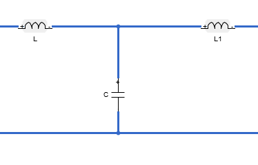
Create a low-pass pi LC ladder object with an inductor value of 3.18e-8 H and a capacitor value of 6.37e-12 F. Calculate and plot the s-parameters.
L = 3.18e-8;
C = [6.37e-12 6.37e-12];
lpp = lcladder('lowpasspi',L,C)
lpp =
lcladder: LC Ladder element
Topology: 'lowpasspi'
Inductances: 3.1800e-08
Capacitances: [6.3700e-12 6.3700e-12]
Name: 'lcfilt'
freq = 0:1e6:1e9;
S = sparameters(lpp,freq);
rfplot(S)

You can also add this LC ladder to a circuit.
c = circuit;
add(c,[1 2 0 0],lpp)
setports(c,[1 0],[2 0])
Design a low-pass pi LC ladder circuit.
L  = 1e-9;
C = [1e-12 1e-12];
lpp = lcladder('lowpasspi',L,C);
Design a default transmission line delay lossy and lossless objects.
tx1 = txlineDelayLossless;
tx2 = txlineDelayLossy;
Create an rfbudget object to design an RF chain.
b = rfbudget([tx1 lpp tx2 ],2.1e9,-30,100e6,Solver="HarmonicBalance")b =
rfbudget with properties:
Elements: [1x3 rf.internal.rfbudget.Element]
InputFrequency: 2.1 GHz
AvailableInputPower: -30 dBm
SignalBandwidth: 100 MHz
Solver: HarmonicBalance
WaitBar: true
AutoUpdate: true
Analysis Results
OutputFrequency: (GHz) [ 2.1 2.1 2.1]
OutputPower: (dBm) [ -30 -30.87 -30.87]
TransducerGain: (dB) [-6.514e-10 -0.868 -0.8683]
NF: (dB) [-2.132e-14 -2.132e-14 0.0003759]
IIP2: (dBm) [ Inf Inf Inf]
OIP2: (dBm) [ Inf Inf Inf]
IIP3: (dBm) [ Inf Inf Inf]
OIP3: (dBm) [ Inf Inf Inf]
SNR: (dB) [ 63.98 63.98 63.97]
Use the show command at the command line to visualize the RF budget chain in the RF Budget Analyzer app. You can also do further analysis on this chain using the app. For more information, see RF Budget Analyzer.
show(b)
