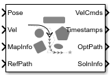
Timed Elastic Band
Libraries:
Navigation Toolbox /
Control Algorithms
Description
The Timed Elastic Band (TEB) block computes a feasible path that avoids obstacles while
guiding the vehicle towards a specified reference path. The reference path is typically
computed using a global path planner like plannerRRTStar.
The local path planner smooths the path while optimizing travel time, and maintains a safe distance from obstacles known or unknown to the global planner.
Examples
Avoid Obstacles Using TEB Local Planner in Simulink
Perform path following using TEB local planner in Simulink.
- Since R2025a
- Open Live Script
Ports
Input
Current pose of the robot, specified as a three-element vector of the form [x y theta]. x and y specify the robot position in meters. theta specifies the robot orientation in radians.
Data Types: single | double | int8 | int16 | int32 | int64 | uint8 | uint16 | uint32 | uint64
Current velocity of the robot, specified as a two-element vector of the form [v w]. v specifies the linear velocity of the robot in meters per second. w specifies the angular velocity of the robot in radians per second.
Data Types: single | double | int8 | int16 | int32 | int64 | uint8 | uint16 | uint32 | uint64
Local map information, specified as a bus. The bus comprises these fields:
Resolution- Grid resolution, specified as a scalar in cells per meter representing the number and size of grid locations.GridLocationInWorld- [x,y] world coordinates of the bottom-left corner of the grid, specified as a 1-by-2 vector.OccpancyMatrix- Occupancy grid values, specified as an h-by-w matrix. h and w are defined by the two elements of theGridSizeproperty of the occupancy grid object.GridSize- Number of rows and columns in grid, specified as a 1-by-2 real-valued vector representing the number of rows and columns, in that order.GridOriginInLocal- Location of the bottom-left corner of the grid in local coordinates, specified as a two-element vector, [xLocal yLocal].
Dependencies
To enable this input port, set the Select Controller Mode
parameter to Path Following with Obstacle
Avoidance.
Data Types: bus
Reference path to follow, specified as an N-by-3 matrix.
Data Types: single | double | int8 | int16 | int32 | int64 | uint8 | uint16 | uint32 | uint64
Maximum limits of linear and angular velocity for velocity commands, specified as a two-element positive vector. The first element is the linear velocity limit, in meters per second, and the second element is the angular velocity limit, in radians per second.
Dependencies
To enable this input port, select the Specify max velocity using
input port checkbox in the Trajectory tab.
Data Types: single | double | int8 | int16 | int32 | int64 | uint8 | uint16 | uint32 | uint64
Maximum velocity of the vehicle while moving in reverse direction, specified as a
positive scalar. When the property is set to NaN, the value of
maximum reverse velocity is same as that of the maximum linear velocity. Units is in
meters per second.
Dependencies
To enable this input port, select the Specify max reverse velocity
using input port checkbox in the Trajectory
tab.
Data Types: single | double | int8 | int16 | int32 | int64 | uint8 | uint16 | uint32 | uint64
Maximum limits of linear and angular acceleration for velocity commands, specified as a two-element positive vector. The first element is the linear acceleration limit, in meters per second squared, and the second element is the angular acceleration limit, in radians per second squared.
Dependencies
To enable this input port, select the Specify max acceleration using
input port checkbox in the Trajectory tab.
Data Types: single | double | int8 | int16 | int32 | int64 | uint8 | uint16 | uint32 | uint64
Minimum turning radius for the vehicle on the optimized path, specified as a nonnegative scalar. This value corresponds to the radius of the turning circle at the maximum steering angle of the vehicle. Units are in meters.
Decrease this value to allow sharp turns and in place rotations. Increase this value to limit sharp turns. When you increase the value, the vehicle will make more forward and reverse motions to turn in a restricted space.
Dependencies
To enable this input port, select the Specify min turning radius
using input port checkbox in the Trajectory
tab.
Data Types: single | double | int8 | int16 | int32 | int64 | uint8 | uint16 | uint32 | uint64
Weight for time, specified as a positive scalar. To lower the travel time, increase this weight value.
Dependencies
To enable this input port, select the Specify time weight using input
port parameter in the Optimization tab .
Data Types: single | double | int8 | int16 | int32 | int64 | uint8 | uint16 | uint32 | uint64
Cost function weight for smooth motion, specified as a positive scalar. To obtain a smoother path, increase this weight value.
Dependencies
To enable this input port, select the Specify smoothness weight using
input port parameter in the Optimization tab
.
Data Types: single | double | int8 | int16 | int32 | int64 | uint8 | uint16 | uint32 | uint64
Cost function weight for maintaining a safe distance from obstacles, specified as a positive scalar.
Dependencies
To enable this input port, set the Select Controller Mode
parameter to Path Following with Obstacle Avoidance and
select the Specify obstacle weight using input port
parameter.
Data Types: single | double | int8 | int16 | int32 | int64 | uint8 | uint16 | uint32 | uint64
Safe distance between the robot and the obstacles, specified as a positive scalar, in meters.
Dependencies
To enable this input port, set the Select Controller Mode
parameter to Path Following with Obstacle Avoidance and
select the Specify obstacle safety margin using input port
parameter.
Data Types: single | double | int8 | int16 | int32 | int64 | uint8 | uint16 | uint32 | uint64
Number of iterations to optimize the trajectory, specified as a positive integer.
Dependencies
To enable this input port, select the Specify number of iterations
using input port checkbox in the Optimization
tab.
Data Types: single | double | int8 | int16 | int32 | int64 | uint8 | uint16 | uint32 | uint64
Lookahead time, specified as a positive scalar in seconds.
Dependencies
To enable this input port, select the Specify lookahead time using
input port checkbox in the Main tab.
Data Types: single | double | int8 | int16 | int32 | int64 | uint8 | uint16 | uint32 | uint64
Tolerance around the goal pose, specified as a three-element vector of the form [x y θ]. x and y denote the position of the robot in x and y directions, respectively. Units are in meters. θ is the heading angle of the robot in radians.
Dependencies
To enable this input port, select the Specify goal tolerance using
input portcheckbox in the Main tab.
Data Types: single | double | int8 | int16 | int32 | int64 | uint8 | uint16 | uint32 | uint64
Reference delta time, specified as a positive scalar in seconds. It specifies the travel time between consecutive poses.
Dependencies
To enable this input port, select the Specify reference delta time
using input port checkbox in the Trajectory
tab.
Data Types: single | double | int8 | int16 | int32 | int64 | uint8 | uint16 | uint32 | uint64
Output
Velocity commands, returned as an N-by-2 matrix. The first column is the linear velocity in meters per second, and the second column is the angular velocity in radians per second.
Data Types: double
Timestamps corresponding to velocity commands, returned as an N-element column vector.
Data Types: double
Optimized path, returned as an N-by-3 matrix. Each row is of the form [x y theta], which defines the xy-position and orientation angle theta at a point in the path.
Data Types: double
Extra information, returned as a bus. The bus comprises these fields:
| Field | Description |
|---|---|
LastFeasibleIdx | Index specifying an element in the optimized path and timestamp
outputs until which the trajectory is feasible. Beyond this index, the
value of |
DistanceFromStartPose | Distance of each pose in |
HasReachedGoal | Indicates whether the robot has successfully reached the last
pose in the ReferencePath within a tolerance, and returns as
|
TrajectoryCost | Cost of optimized trajectory for cost functions in the Timed Elastic Band algorithm. |
ExitFlag | Scalar value indicating the exit condition of the
|
The bus is defined using this function in the InitFcn block
callback parameter of the Callbacks section. On the
Modelling tab, under Design, on the Properties tab of the
Property Inspector, you can find the Callbacks
section.
extraInfo_bus = nav.slalgs.internal.utils.extraInfo(); extraInfo_bus.Elements(2).Dimensions = [1000 1]; extraInfo_bus.Elements(2).DimensionsMode = "Variable";
Data Types: bus
Parameters
To edit block parameters interactively, use the Property Inspector. From the Simulink® Toolstrip, on the Simulation tab, in the Prepare gallery, select Property Inspector.
Since R2026a
Specify the controller mode as Path Following with Obstacle
Avoidance or Path Following.
Path Following with Obstacle Avoidance— Specify for path following with obstacle avoidance.Path Following— Specify for path following in an obstacle free environment. This mode does not require map input.
Main Tab
Specify sample time of the controller in seconds. This block only supports discrete sample time.
Select this check box to add an input port for specifying the Lookahead time (s) parameter.
Specify lookahead time as a positive scalar. Units in seconds. The controller generates velocity commands and optimizes the trajectory until the controller reaches the lookahead time. A higher lookahead time generates velocity commands further into the future. This enables the robot to react earlier to unseen obstacles, but increases the controller execution time. Conversely, a shorter lookahead time reduces the available time to react to new, unknown obstacles, but enables the controller to run at a faster rate.
Dependencies
To enable this parameter, clear the Specify lookahead time using input port checkbox.
Select this checkbox to add an input port for specifying the Goal tolerance ([m m rad]) parameter.
Specify the tolerance around goal pose as a three-element vector of the form [x y θ]. x and y denote the position of the robot in x and y directions, respectively. Units are in meters. θ is the heading angle of the robot in radians. This goal tolerance value specifies the limit for determining whether the robot has reached the goal pose.
Dependencies
To enable this parameter, clear the Specify goal tolerance using input port checkbox.
Trajectory Tab
Select this checkbox to add an input port for specifying the Maximum velocity ([m/s rad/s]) parameter.
Maximum limits of linear and angular velocity for velocity commands, specified as a two-element positive vector. The first element is the linear velocity limit, in meters per second, and the second element is the angular velocity limit, in radians per second.
Dependencies
To enable this parameter, clear the Specify max velocity using input port checkbox.
Select this checkbox to add an input port for specifying the Maximum reverse velocity (m/s) parameter.
Maximum velocity of the vehicle while moving in reverse direction, specified as a
positive scalar. The default value is NaN. When the property is set
to NaN, the value of maximum reverse velocity is same as that of the
maximum linear velocity. Units is in meters per second.
Dependencies
To enable this parameter, clear the Specify max reverse velocity using input port checkbox.
Select this checkbox to add an input port for specifying the Maximum acceleration ([m/s^2 rad/s^2]) parameter.
Maximum limits of linear and angular acceleration for velocity commands, specified as a two-element positive vector. The first element is the linear acceleration limit, in meters per second squared, and the second element is the angular acceleration limit, in radians per second squared.
Dependencies
To enable this parameter, clear the Specify max acceleration using input port checkbox.
Select this checkbox to add an input port for specifying the Minimum turning radius (m) parameter.
Minimum turning radius for the vehicle on the optimized path, specified as a nonnegative scalar. This value corresponds to the radius of the turning circle at the maximum steering angle of the vehicle. Units are in meters.
Decrease this value to allow sharp turns and in place rotations. Increase this value to limit sharp turns. When you increase the value, the vehicle will make more forward and reverse motions to turn in a restricted space.
Dependencies
To enable this parameter, clear the Specify min turning radius using input port checkbox.
Select this checkbox to add an input port for specifying the Reference delta time (s) parameter.
Reference delta time, specified as a positive scalar in seconds. It specifies the travel time between consecutive poses. This parameter affects the addition and deletion of poses for the optimized trajectory. Increase the value of this parameter to have fewer poses and reduce it to have more poses in the output path.
Dependencies
To enable this parameter, clear the Specify reference delta time using input port checkbox.
Optimization Tab
Select this checkbox to add an input port for specifying the Number of iterations parameter.
Number of iterations to optimize the trajectory, specified as a positive integer. This value is the number of times interpolation occurs and the controller calls the solver for trajectory optimization.
Dependencies
To enable this parameter, clear the Specify number of iterations using input port checkbox.
Select this checkbox to add an input port for specifying the Time weight parameter.
Cost function weight for time, specified as a positive scalar. To lower the travel time, increase this weight value.
Dependencies
To enable this parameter, clear the Specify time weight using input port checkbox.
Select this checkbox to add an input port for specifying the Smoothness weight parameter.
Cost function weight for smooth motion, specified as a positive scalar. To obtain a smoother path, increase this weight value.
Dependencies
To enable this parameter, clear the Specify smoothness weight using input port checkbox.
Select this checkbox to add an input port for specifying the Obstacle weight parameter.
Dependencies
To enable this parameter, set the Select Controller Mode
parameter to Path Following with Obstacle Avoidance.
Cost function weight for maintaining a safe distance from obstacles, specified as a positive scalar. To prioritize maintaining a safe distance from obstacles, increase this weight value.
Dependencies
To enable this parameter, set the Select Controller Mode
parameter to Path Following with Obstacle Avoidance and
clear the Specify obstacle weight using input port
parameter.
Obstacle Avoidance Tab
Since R2026a
Specify the shape of the robot as Rectangle or
Point.
Dependencies
To enable this parameter, set the Select Controller Mode
parameter to Path Following with Obstacle Avoidance.
Specify the size of the robot as a two-element positive vector of the form [length width], in meters.
Dependencies
To enable this parameter, set the Select Controller Mode
parameter to Path Following with Obstacle Avoidance.
Transformation matrix, specified as an se2 object
defining an SE(2) transformation matrix or three-element row vector representing the
origin of the robot. The vector is of the form [x,
y, theta]. When you specify the origin as
[x, y, theta], the
Timed Elastic Band block computes the associated SE(2) transformation
matrix and stores it in the FixedTransform field.
The default origin is at the center of the rear end of the robot. You can use this parameter to specify a new origin for the robot relative to the default origin.
This parameter is valid only if the robot is of rectangular shape.
Dependencies
To enable this parameter, set the Select Controller Mode
parameter to Path Following with Obstacle Avoidance.
Select this checkbox to add an input port for specifying the Obstacle safety margin (m) parameter.
Dependencies
To enable this parameter, set the Select Controller Mode
parameter to Path Following with Obstacle Avoidance.
Safe distance between the robot and the obstacles, specified as a positive scalar, in meters.
Dependencies
To enable this parameter, set the Select Controller Mode
parameter to Path Following with Obstacle Avoidance and
clear the Specify obstacle safety margin using input port
parameter.
Extended Capabilities
C/C++ Code Generation
Generate C and C++ code using Simulink® Coder™.
Version History
Introduced in R2025aThe extra information returned as SolnInfo output bus is now defined using
this function in the InitFcn block callback parameter of the Callbacks
section. On the
Modelling tab, under Design, on the Properties tab of the
Property Inspector, you can find the Callbacks
section.
extraInfo_bus = nav.slalgs.internal.utils.extraInfo();
extraInfo_bus.Elements(2).Dimensions = [1000 1];
extraInfo_bus.Elements(2).DimensionsMode = "Variable";
You can now use the block for path following in an obstacle free environment by setting
the new Select Controller Mode parameter to Path
Following. This mode does not require map input. The parameters for
specifying robot information (Shape,
Dimension, Fixed transform) and the parameters
for specifying map information (Specify obstacle safety margin using input
port and Obstacle safety margin) have moved from the
Main tab to the new Obstacle
Avoidance tab. The behavior of these parameters remains the same.
See Also
Objects
Blocks
MATLAB Command
You clicked a link that corresponds to this MATLAB command:
Run the command by entering it in the MATLAB Command Window. Web browsers do not support MATLAB commands.
Select a Web Site
Choose a web site to get translated content where available and see local events and offers. Based on your location, we recommend that you select: .
You can also select a web site from the following list
How to Get Best Site Performance
Select the China site (in Chinese or English) for best site performance. Other MathWorks country sites are not optimized for visits from your location.
Americas
- América Latina (Español)
- Canada (English)
- United States (English)
Europe
- Belgium (English)
- Denmark (English)
- Deutschland (Deutsch)
- España (Español)
- Finland (English)
- France (Français)
- Ireland (English)
- Italia (Italiano)
- Luxembourg (English)
- Netherlands (English)
- Norway (English)
- Österreich (Deutsch)
- Portugal (English)
- Sweden (English)
- Switzerland
- United Kingdom (English)