Main Content

rgbdvslam

Feature-based visual simultaneous localization and mapping (vSLAM) and visual-inertial sensor fusion with RGB-D camera

Since R2025a

    Description

    Use the rgbdvslam object to perform visual simultaneous localization and mapping (vSLAM) with RGB-D camera data. RGB-D vSLAM combines depth information from sensors, such as RGB-D cameras or depth sensors, with RGB images to simultaneously estimate the camera pose and create a map of the environment. To learn more about visual SLAM, see Implement Visual SLAM in MATLAB (Computer Vision Toolbox).

    The rgbdvslam object extracts Oriented FAST and Rotated BRIEF (ORB) features from incrementally read images, and then tracks those features to estimate camera poses, identify key frames, and reconstruct a 3-D environment. The vSLAM algorithm also searches for loop closures using the bag-of-features algorithm, and then optimizes the camera poses using pose graph optimization. You can enhance the accuracy and robustness of the SLAM by integrating this object with IMU data to perform visual-inertial sensor fusion.

    Creation

    Description

    vslam = rgbdvslam(intrinsics) creates an RGB-D visual SLAM object, vslam, by using the specified camera intrinsic parameters.

    The rgbdvslam object assumes the color and the depth images have been preregistered with one-to-one correspondence.

    The object represents 3-D map points and camera poses in world coordinates, and assumes the camera pose of the first key frame is an identity rigidtform3d (Image Processing Toolbox) transform.

    Note

    The rgbdvslam object runs on multiple threads internally, which can delay the processing of an image frame added by using the addFrame function. Additionally, the object running on multiple threads means the current frame the object is processing can be different than the recently added frame.

    vslam = rgbdvslam(intrinsics,depthScaleFactor) specifies the depth correction factor of the RGB-D camera, which the camera manufacturer usually provides. Use this syntax when the depth scale factor for the sensor is not equal to 1.

    vslam = rgbdvslam(___,imuParameters) performs RGB-D visual-inertial SLAM based on the specified imuParameters.

    vslam = rgbdvslam(intrinsics,PropertyName=Value) sets properties using one or more name-value arguments. For example, MaxNumPoints=850 sets the maximum number of ORB feature points to extract from each image to 850.

    example

    Input Arguments

    expand all

    Camera intrinsic parameters, specified as a cameraIntrinsics (Computer Vision Toolbox) object.

    This argument sets the Intrinsics property.

    Depth scale factor, specified as a scalar in real-world units, such as meters. The depth scale factor is the conversion factor that relates the depth values of the depth sensor to real-world distances, and is typically expressed in the same units as the depth measurements provided by the sensor, such as millimeters, centimeters, or meters. This value provides the necessary information to transform the depth measurements into the metric scale. Use the depthScaleFactor argument when the value for the sensor you are using is not equal to 1.

    For the world 3-D coordinates (X, Y, Z), where Z is the depth at any pixel coordinate (u, v), Z = P/depthScaleFactor, where P represents the intensity value of the depth image at pixel (u, v).

    This argument sets the DepthScaleFactor property.

    IMU parameters, specified as a factorIMUParameters object. The object contains the noise, bias, and sample rate information about the inertial measurement unit (IMU).

    Properties

    expand all

    Camera Parameters

    This property is read-only.

    Camera intrinsic parameters, stored as a cameraIntrinsics (Computer Vision Toolbox) object.

    Use the intrinsics argument to set this property.

    This property is read-only after object creation.

    Depth scale factor, specified as a scalar in real-world units (e.g., meters). The depth scale factor depends on the depth sensor, and it is typically expressed in the same unit as the depth measurements provided by the sensor (e.g., millimeters, centimeters, or meters). It is the conversion factor that relates the depth values to real-world distances. In other words, it provides the necessary information to transform the depth measurements into metric scale.

    For the world 3-D coordinates (X,Y,Z), where Z represents depth at any pixel coordinate (u,v), Z would be computed as Z = P/depthScaleFactor, where P represents the intensity value of the depth image at pixel (u,v).

    Use the depthScaleFactor argument to set this property.

    This property is read-only after object creation.

    Depth range of the RGB-D camera, specified as a two-element vector, in world units. The range specifies the minimum and maximum depth values of the camera, which you can use to filter out invalid depth values in the depth images.

    Feature Extraction

    This property is read-only after object creation.

    Scale factor for image decomposition, stored as a scalar greater than 1. The scale factor is also referred to as the pyramid decimation ratio. Increasing the value of ScaleFactor reduces the number of pyramid levels, but reduce computation time. Decreasing this value (down to just over 1), increases the number of pyramid levels, which can improve tracking performance, at the cost of computation speed. The scale value at each level of decomposition is ScaleFactor(level-1), where level is any value in the range [0, Numlevels-1]. Given the input image of size M-by-N, the image size at each level of composition is Mlevel-by-Nlevel, where:

    Mlevel=MScaleFactor(level1)Nlevel=NScaleFactor(level1)

    This property is read-only after object creation.

    Number of decomposition levels, specified as an integer greater than or equal to 1. Increase this value to extract keypoints from the image at more levels of decomposition. Along with the ScaleFactor value, NumLevels controls the number of pyramid levels on which the object evaluates feature points.

    The image size at each decomposition level limits the number of levels at which you can extract keypoints. The image size at a level of decomposition must be at least 63-by-63 for keypoint detection. The maximum level of decomposition is calculated as

    levelmax = floor(log(min(M,N))log(63)log(ScaleFactor))+1

    If either the default value or the specified value of NumLevels is greater than levelmax, the object modifies NumLevels to levelmax and returns a warning.

    This property is read-only after object creation.

    Maximum number of ORB feature points uniformly extracted from each image, specified as a positive integer. Values are typically in the range of [800, 2000], depending on the resolution of the image. When the number of extracted features is less than the value of MaxNumPoints, then the object uses all feature points.

    Tracking

    This property is read-only after object creation.

    Key frame feature point range, stored as a two-element vector of positive integers in the form [lowerLimit upperLimit]. This property specifies the minimum and maximum numbers of tracked features points a frame must contain for the object to identify it as a key frame. The TrackFeatureRange and the SkipMaxFrames properties enable you to control the frequency at which frames in the tracking process become key frames.

    The success of tracking depends on the number of tracked points in the current frame, with one of these results:

    • Tracking is lost — The number of tracked feature points in the current frame is less than the lowerLimit set by the TrackFeatureRange argument. This indicates that the image does not contain enough features, or that the camera is moving too fast. To improve the tracking, you can increase the upperLimit value of the TrackFeatureRange property and decrease the SkipMaxFrames property to add key frames more frequently.

    • Tracking is successful — The object identifies the current frame as a key frame. The number of tracked feature points in the current frame is in the range set by TrackFeatureRange.

    • Tracking adds key frames too frequently — The number of tracked feature points in the current frame is greater than the upperLimit set by the TrackFeatureRange property. This indicates that the camera is moving very slowly, which produces an unnecessary number of key frames. To improve the tracking, you can reduce the frequency of adding key frames by increasing the value of the SkipMaxFrames property.

    For more details, see the addFrame object function.

    This property is read-only after object creation.

    Maximum number of skipped frames, stored as a positive integer. When the number of tracked features is consistently greater than the upperLimit set by the TrackFeatureRange property, use the SkipMaxFrames property to control the frequency at which the object adds new key frames. The object identifies the current frame as a key frame when the number of skipped frames since the most recently added key frame equals the value of SkipMaxFrames.

    This property is read-only after object creation.

    Minimum number of matched feature points between loop closure key frames, stored as a positive integer.

    This property is read-only after object creation.

    Custom bag of features for loop detection, specified as a bagOfFeaturesDBoW (Computer Vision Toolbox) object. The bagOfFeaturesDBoW (Computer Vision Toolbox) enables you to create a custom bag of words (BoW) from feature descriptors, alongside options to utilize a built-in vocabulary or load a custom one from a specified file.

    This property is read-only after object creation.

    Progress information display, specified as [], 1, 2, or 3. Paths to the location of log files, when they are created, is displayed on the command line.

    Verbose valueDisplay descriptionDisplay location
    [] or falseDisplay is turned off
    1 or trueStages of vSLAM executionCommand window
    2Stages of vSLAM execution, with details on how the frame is processed, such as the artifacts used to initialize the map. Log file in a temporary folder
    3Stages of vSLAM, artifacts used to initialize the map, poses and map points before and after bundle adjustment, and loop closure optimization data.Log file in a temporary folder

    IMU Fusion

    This property is read-only after object creation.

    IMU sensor transformation, specified as a rigidtform3d (Image Processing Toolbox) object. The transformation describes the rotation and translation of the camera in the coordinate system of the IMU sensor.

    This property is read-only after object creation.

    Number of estimated camera poses to trigger camera-IMU alignment, specified as an integer equal to or greater than 2. The process of aligning camera and IMU data is initiated after a specific number of camera poses have been estimated. This alignment serves two primary purposes: first, to estimate a scale factor that translates the up-to-scale results from a monocular camera into actual world units (meters), and second, to synchronize the IMU and camera frames, effectively eliminating the influence of gravity on accelerometer data. The timing for this alignment, determined by a threshold for the number of camera poses, is key to its success. A threshold set too low may not provide enough data for accurate calibration, while one set too high risks incorporating noise from measurement drift into the calibration. For a more in-depth understanding of this calibration technique, see the estimateGravityRotationAndPoseScale function.

    This property is read-only after object creation.

    Subset of pose estimates, specified as a scalar in the range of (0,1]. This value specifies a fraction of the number of recent pose estimates, calculated as round(NumPosesThreshold*AlignmentFraction), for use in the camera-IMU alignment process. It effectively filters out initial, potentially noisy pose estimates, ensuring only the most relevant data contributes to the alignment for improved accuracy.

    Object Functions

    addFrameAdd pair of color and depth images to RGB-D visual SLAM object
    hasNewKeyFrameCheck if new key frame added in RGB-D visual SLAM object
    checkStatusCheck status of visual RGB-D SLAM object
    isDoneEnd-of-processing status for RGB-D visual SLAM object
    mapPointsBuild 3-D map of world points from RGB-D vSLAM object
    posesAbsolute camera poses of RGB-D vSLAM key frames
    plotPlot 3-D map points and estimated camera trajectory in RGB-D visual SLAM
    resetReset RGB-D visual SLAM object

    Examples

    collapse all

    Perform RGB-D visual simultaneous localization and mapping (vSLAM) using the data from the TUM RGB-D Benchmark. You can download the data to a temporary directory using a web browser or by running this code:

    baseDownloadURL = "https://vision.in.tum.de/rgbd/dataset/freiburg3/rgbd_dataset_freiburg3_long_office_household.tgz"; 
    dataFolder = fullfile(tempdir,"tum_rgbd_dataset",filesep); 
    options = weboptions(Timeout=Inf);
    tgzFileName = dataFolder+"fr3_office.tgz";
    folderExists = exist(dataFolder,"dir");
    
    % Create a folder in a temporary directory to save the downloaded file
    if ~folderExists  
        mkdir(dataFolder) 
        disp("Downloading fr3_office.tgz (1.38 GB). This download can take a few minutes.") 
        websave(tgzFileName,baseDownloadURL,options); 
        
        % Extract contents of the downloaded file
        disp("Extracting fr3_office.tgz (1.38 GB) ...") 
        untar(tgzFileName,dataFolder); 
    end

    Create two imageDatastore objects. One to store the color images and the other to store the depth images.

    colorImageFolder = dataFolder+"rgbd_dataset_freiburg3_long_office_household/rgb/";
    depthImageFolder = dataFolder+"rgbd_dataset_freiburg3_long_office_household/depth/";
    
    imdsColor = imageDatastore(colorImageFolder);
    imdsDepth = imageDatastore(depthImageFolder);

    Select the synchronized pair of color and depth images.

    data = load("rgbDepthPairs.mat");
    imdsColor=subset(imdsColor, data.indexPairs(:, 1));
    imdsDepth=subset(imdsDepth, data.indexPairs(:, 2));

    Specify your camera intrinsic parameters, and use them to create an RGB-D visual SLAM object.

    intrinsics = cameraIntrinsics([535.4 539.2],[320.1 247.6],[480 640]);
    depthScaleFactor = 5000;
    vslam = rgbdvslam(intrinsics,depthScaleFactor);

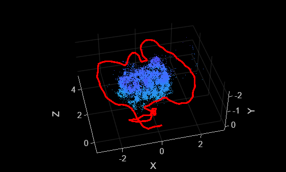
    Process each pair of color and depth images, and visualize the camera poses and 3-D map points.

    for i = 1:numel(imdsColor.Files)
        colorImage = readimage(imdsColor,i);
        depthImage = readimage(imdsDepth,i);
        addFrame(vslam,colorImage,depthImage);
    
        if hasNewKeyFrame(vslam)
            % Query 3-D map points and camera poses
            xyzPoints = mapPoints(vslam);
            [camPoses,viewIds] = poses(vslam);
    
            % Display 3-D map points and camera trajectory
            plot(vslam);
        end
    
        % Get current status of system
        status = checkStatus(vslam);
        
        % Stop adding frames when tracking is lost
        if status == uint8(0)
            break
        end
    end 

    Figure contains an axes object. The axes object with xlabel X, ylabel Y contains 12 objects of type line, text, patch, scatter. This object represents Camera trajectory.

    Once all the frames have been processed, reset the system.

    while ~isDone(vslam)
        plot(vslam);
    end

    Figure contains an axes object. The axes object with xlabel X, ylabel Y contains 12 objects of type line, text, patch, scatter. This object represents Camera trajectory.

    reset(vslam);

    Perform RGB-D visual-inertial SLAM using the data from the OpenLORIS-Scene Dataset. Download the data to a temporary directory using a web browser or by running this code:

    dataFolder  = fullfile(tempdir,"OpenLORIS-Scene",filesep); 
    downloadURL = "https://ssd.mathworks.com/supportfiles/shared_nav_vision/data/OpenLORIS-Scene_corridor1-4.zip";
    zipFileName = dataFolder+"corridor1-4.zip";
    
    if ~isfolder(dataFolder)
        mkdir(dataFolder);
        disp("Downloading corridor1-4.zip (1.13 GB). This download can take a few minutes.");
        options = weboptions('Timeout', Inf);
        websave(zipFileName, downloadURL, options); 
        unzip(zipFileName, dataFolder);
    end

    Create two imageDatastore objects. One to store the color images and the other to store the depth images.

    imageFolder = fullfile(dataFolder,"OpenLORIS-Scene_corridor1-4");
    imdsColor = imageDatastore(fullfile(imageFolder,"color"));
    imdsDepth = imageDatastore(fullfile(imageFolder,"aligned_depth"));

    Load the IMU measurements data and the camera-to-IMU transform.

    data    = load("corridor4_IMU_data.mat");
    gyro    = data.gyroDataCell;
    accel   = data.accelDataCell;
    cam2IMU = data.cam2IMU;

    Specify the camera intrinsics, the IMU parameters, and use them to create an RGB-D visual-inertial SLAM object.

    % Camera intrinsic and IMU parameters can be found in the downloaded  
    % sensors.yaml file
    intrinsics = cameraIntrinsics([6.1145098876953125e+02, 6.1148571777343750e+02],...
        [4.3320397949218750e+02, 2.4947302246093750e+02], [480, 848]);
    
    imuParams = factorIMUParameters(AccelerometerBiasNoise=2.499999936844688e-05*eye(3),...
           AccelerometerNoise=0.00026780980988405645*eye(3),...
           GyroscopeNoise=1.0296060281689279e-05*eye(3),...
           GyroscopeBiasNoise=2.499999993688107e-07*eye(3),...
           SampleRate=250);
    
    depthScaleFactor = 1000;
    vslam = rgbdvslam(intrinsics, depthScaleFactor, imuParams, SkipMaxFrames=10,...
        CameraToIMUTransform=cam2IMU, TrackFeatureRange = [30, 150], DepthRange= [0.1, 6.5], ...
        NumPosesThreshold=20, MaxNumPoints=1.2e3);

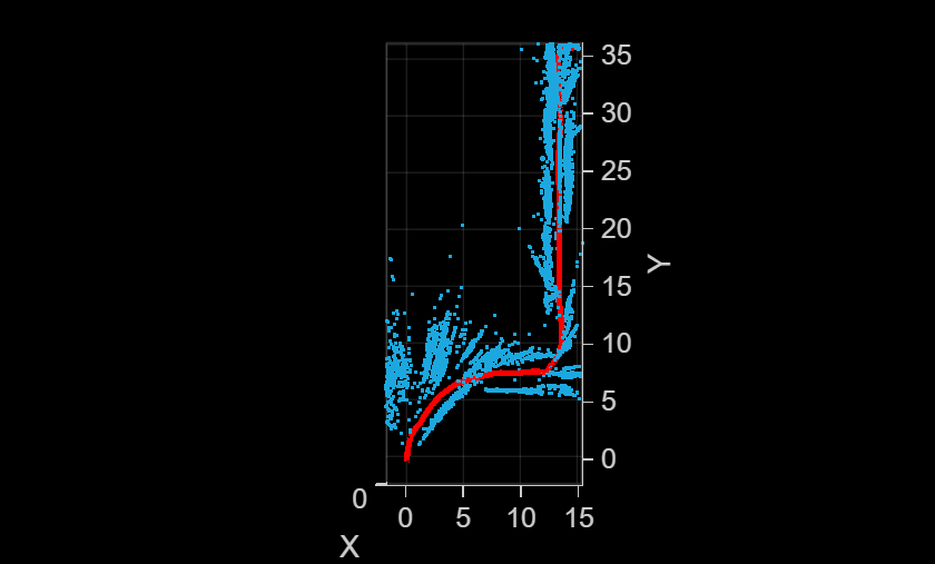
    Process image data and IMU data, and visualize the camera poses and 3-D map points.

    for i = 1:numel(imdsColor.Files)
        colorImage  = readimage(imdsColor,i);
        depthImage  = readimage(imdsDepth,i);
        addFrame(vslam, colorImage, depthImage, gyro{i}, accel{i});
    
        if hasNewKeyFrame(vslam)
            plot(vslam);
        end
    end

    Once all the frames have been processed, reset the system.

    while ~isDone(vslam)
        if hasNewKeyFrame(vslam)
            ax = plot(vslam);
        end
    end
    view(ax, 0, 90)

    Figure contains an axes object. The axes object with xlabel X, ylabel Y contains 12 objects of type line, text, patch, scatter. This object represents Camera trajectory.

    reset(vslam);

    References

    [1] Mur-Artal, Raul, J. M. M. Montiel, and Juan D. Tardos. “ORB-SLAM: A Versatile and Accurate Monocular SLAM System.” IEEE Transactions on Robotics 31, no. 5 (October 2015): 1147–63. https://doi.org/10.1109/TRO.2015.2463671.

    Extended Capabilities

    expand all

    Version History

    Introduced in R2025a

    expand all

    See Also

    Objects

    Functions

    External Websites