Solenoid Valve (IL)

Libraries:
Simscape /
Fluids /
Isothermal Liquid /
Valves & Orifices /
Directional Control Valves
Description
The Solenoid Valve (IL) block models flow through a solenoid valve in an isothermal liquid network. The valve consists of a two-way directional control valve with a solenoid actuator. The physical signal at port S controls the solenoid. When the signal at port S is above 0.5, the solenoid turns on and the valve opens. When the signal at port S falls below 0.5, the solenoid turns off, closing the valve.
A solenoid valves consists of a valve body with a spring-loaded plunger that is operated by an electric solenoid. When the solenoid is on, the magnetic force lifts the spool, allowing fluid to flow. When the solenoid is off, the spring pushes the plunger back in place, stopping flow. The block does not model the mechanics of the solenoid explicitly, but characterizes the opening and closing of the valve using the opening and closing switching times.
Mass Flow Rate
The mass flow rate through the valve is
where:
A is the cross-sectional area of the valve.
Aport is the value of the Cross-sectional area at ports A and B parameter.
Cd is the value of the Discharge coefficient parameter.
is the average fluid density in the valve.
Δp is the change in pressure across the valve.
Δpcrit is the critical pressure,
where Recrit is the value of the Critical Reynolds number parameter and μ is the fluid viscosity.
Opening Dynamics
The block assumes that the solenoid behaves as a resistor-inductor series circuit, represented as
where:
V is the voltage across solenoid inductor.
R is the resistance of the solenoid inductor.
L is the inductance of the solenoid.
i is the current through the solenoid inductor.
The solenoid generates a force proportional to the current squared, where K is a proportionality constant. The expression for the cross-sectional area of the valve, A(t), depends on the value of the Solenoid control parameter.
When you set Solenoid control to Physical
signal, the block calculates the opening area based on the
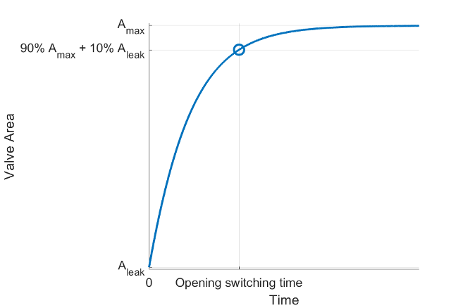
signal at port S. When the valve is opening,
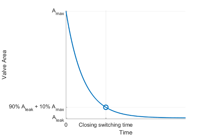
When the valve is closing,
where:
Amax is the value of the Maximum opening area parameter.
Aleak is the value of the Leakage area parameter.
tstart is the time that the solenoid turns on or off.
A0 is the valve area at the time the solenoid turns on or off.
where tswitchopen is the value of the Opening switching time parameter.
where tswitchclose is the value of the Closing switching time parameter.
When you set Solenoid control to
Electrical ports, the block calculates the
opening area based on the electrical network connected to the solenoid valve at
ports + and -.
The opening area is
where x is the plunger position and l is the value of the Plunger distance of travel parameter.
The block models the plunger motion with the force balance expression
where:
mcore is the mass of the moving parts in the solenoid valve.
Fspring is the force exerted by the spring to close the valve when the solenoid is off.
Fhardstop is the hard-stop force that prevents the plunger from moving beyond the fully open and fully closed positions. The block calculates the hard-stop by using mode charts. For more information, see Mode Chart Modeling.
Fmagnetic is the force generated by the solenoid,
The block uses the solution to the force balance expression to calculate mcore, Fspring, and K at the values of the Rated voltage, Nominal current, Opening switching time, and Closing switching time parameters. The block then uses these values for mcore, Fspring, and K to solve for the plunger position at all other times.
Switching Time
The block characterizes the solenoid valve by using the valve opening and closing switching times specified by the Opening switching time, and Closing switching time parameters, respectively. The Opening switching time parameter is the time from the solenoid being turned on to the flow rate rising to 90% of the way between its maximum and minimum values.
The Closing switching time parameter is the time from the solenoid being turned off to the flow rate falling to 10% of the way between its maximum and minimum values.
Assumptions and Limitations
The maximum solenoid force is the same as the force generated by the spring.
The damping inside the solenoid and the pressure flow forces are negligible.
The spool is balanced.
The solenoid travel distance is short enough that the block assumes the inductance is linear.
Ports
Input
Conserving
Parameters
References
[1] Zhang, Xiang, Yonghua Lu, Yang Li, Chi Zhang, and Rui Wang. “Numerical Calculation and Experimental Study on Response Characteristics of Pneumatic Solenoid Valves.” Measurement and Control 52, no. 9–10 (November 2019): 1382–93. https://doi.org/10.1177/0020294019866853.
[2] Zhang, Jianyu, Peng Liu, Liyun Fan, and Yajie Deng. “Analysis on Dynamic Response Characteristics of High-Speed Solenoid Valve for Electronic Control Fuel Injection System.” Mathematical Problems in Engineering 2020 (January 22, 2020): 1–9. https://doi.org/10.1155/2020/2803545.