Rotating Single-Acting Actuator (IL)
R2026bActuator on a rotating shaft in an isothermal liquid network
Rotating Single-Acting Actuator (IL) block

To add a block to a model, double-click the canvas and start typing the block name. Then, select the block from the list.
Libraries:
Simscape /
Fluids /
Isothermal Liquid /
Actuators
Description
The Rotating Single-Acting Actuator (IL) block models an actuator that rotates around its central axis in an isothermal liquid network. Rotating shaft control components such as friction clutches or brakes may use rotating actuators. The fluid enters the actuator at port A. The angular velocity is set at port W. Port C is associated with the actuator casing and the piston velocity and force are set at port R.
When the block internally calculates the piston position, port p outputs the piston position. When a connection to a Simscape™ Multibody™ joint sets the position, the block receives the position as a physical signal at port p. One of four hard stop models limits the motion of the piston when it is near full extension or full retraction.
Geometry
The cylinder chamber of the actuator is an annulus with an inner radius equal to the value of the Piston inner radius parameter and an outer radius equal to the value of the Piston outer radius parameter. The fluid enters the cylinder chamber at the radius specified by the Fluid channel length parameter. The fluid enters the entire component along the axis of rotation. The value of the Fluid channel length parameter must be between the value of the Piston inner radius and Piston outer radius parameters.
Displacement
The piston displacement is measured as the position at port R relative
to port C. The Mechanical orientation
parameter identifies the direction of piston displacement. The piston displacement
is neutral, or 0, when the chamber volume is equal to the value
of the Dead volume parameter. If you specify the displacement
with an input, ensure that the derivative of the position is equal to the piston
velocity. If you specify the input with a Translational Multibody Interface block
connection to a Simscape Multibody joint, this requirement is met.
Hard Stop Model
To avoid mechanical damage to an actuator when it is fully extended or fully retracted, an actuator typically has nonlinear behavior when the piston approaches these limits. The Rotating Single-Acting Actuator (IL) block models this behavior with a choice of four hard stop models, which model the material compliance through a spring-damper system. The hard stop models are:
Stiffness and damping applied smoothly through transition region, damped rebound.Full stiffness and damping applied at bounds, undamped rebound.Full stiffness and damping applied at bounds, damped rebound.Based on coefficient of restitution
The block models the hard stop force when the piston is at its upper or lower bound. The boundary region is within the value of the Transition region parameter relative to the value of the Piston stroke parameter or the piston initial displacement. Outside of this region,
For more information about these settings, see the Translational Hard Stop block page.
Block Subcomponents
The Rotating Single-Acting Actuator (IL) block is a composite component that comprises three blocks:
Rotating Channel (IL) — This subcomponent moves the fluid from a radius of 0 to a radius equal to the value of the Fluid channel length parameter and accounts for the pressure change due to the centrifugal effect of the change in radius.
Single-Acting Actuator (IL) — This subcomponent calculates the actuator force from the pressure of the fluid that enters the cylinder chamber, which includes the centrifugal effect of moving the fluid to the fluid channel length.
Rotating Cylinder Force (IL) — The fluid inside the chamber has a pressure gradient due to the centrifugal effect. This subcomponent accounts for the change in the actuator force due to the pressure gradient relative to the pressure at the radius equal to the value of the Fluid channel length parameter.
This figure shows the functional block diagram for the Rotating Single-Acting Actuator (IL) block.

Examples
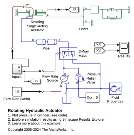
Rotating Hydraulic Actuator
Uses a Rotating Single-Acting Actuator (IL) block to model a hydraulic cylinder actuator for operating friction clutches, brakes, and other devices installed on rotating shafts. A key element of the actuator is a piston that moves back and forth under an axial force that consists of the static pressure force and a rotating cylinder force developed by centrifugal force on the rotating fluid.

