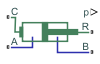
Double-Acting Actuator (IL)
Linear conversion of pressure differential to actuation in an isothermal liquid system
Libraries:
Simscape /
Fluids /
Isothermal Liquid /
Actuators
Description
The Double-Acting Actuator (IL) block represents the linear conversion of a pressure differential between two chambers to piston motion. The piston actuation is controlled by the pressure differential acting on the piston plate that separates the chambers. The motion of the piston when it is near full extension or full retraction is limited by one of four hard stop models. Fluid compressibility is optionally modeled in both piston chambers.
Ports A and B are isothermal liquid inlets. Port C represents the actuator casing, while piston velocity is returned at port R. When the piston position is calculated internally, it is reported at port p, and when the position is set by a connection to a Simscape™ Multibody™ joint, it is received as a physical signal at port p.
You can define the piston displacement direction with the Mechanical
orientation parameter. If the mechanical orientation is set to
Pressure at A causes positive displacement of R relative to
				C
, the piston extends when the pressure differential
pA –
pB is positive. If Mechanical
orientation is set to Pressure at A causes negative
displacement of R relative to C, the piston retracts for a positive
pressure difference between the liquid and gas chambers.
Displacement
The piston displacement is measured as the position at port R relative
to port C. The Mechanical orientation
identifies the direction of piston displacement. The piston displacement is neutral,
or 0, when the chamber A volume is equal to the chamber dead
volume. When displacement is received as an input, ensure that the derivative of the
position is equal to the piston velocity. This is automatically the case when the
input is received from a Translational Multibody Interface block
connection to a Simscape Multibody joint.
Hard Stop Model
To avoid mechanical damage to an actuator when it is fully extended or fully retracted, an actuator typically displays nonlinear behavior when the piston approaches these limits. The Double-Acting Actuator (IL) block models this behavior with a choice of four hard stop models, which model the material compliance through a spring-damper system. The hard stop models are:
Stiffness and damping applied smoothly through transition region, damped rebound.Full stiffness and damping applied at bounds, undamped rebound.Full stiffness and damping applied at bounds, damped rebound.Based on coefficient of restitution
The hard stop force is modeled when the piston is at its upper or lower bound. The boundary region is within the Transition region of the Piston stroke or piston initial displacement. Outside of this region,
For more information about these settings, see the Translational Hard Stop block page.
Cushion
The block can model cushioning toward the extremes of the piston stroke. Select Cylinder end cushioning to slow the piston motion as it approaches the maximum extension, defined by the Piston stroke parameter. For more information on the functionality of a cylinder cushion, see the Cylinder Cushion (IL) block.
Friction
The block can model friction against piston motion. When you select Cylinder friction, the resulting friction is a combination of the Stribeck, Coulomb, and viscous effects. The block measures the pressure difference between the chamber pressure and the environment pressure. For more information on the friction model and its limitations, see the Cylinder Friction (IL) block.
Numerically-Smoothed Area and Pressure
You can maintain numerical robustness in your simulation by adjusting the Smoothing factor parameter. If the Smoothing factor parameter is nonzero, the block smooths the cushion A and B orifice areas and the check valve pressure ranges. The orifice area is smoothly saturated between the cushion A and cushion B Leakage area between plunger and cushion sleeve and Cushion plunger cross-sectional area parameters while the valve pressure is saturated between the cushion A and cushion B Check valve cracking pressure differential and Check valve maximum pressure differential parameters. For more information, see Numerical Smoothing.
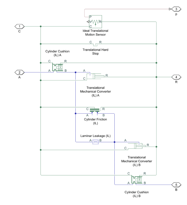
Block Schematic
The Double-Acting Actuator (IL) block comprises four Simscape Foundation blocks:
and two Isothermal Liquid library blocks:
Momentum Balance
The momentum conservation equation for the actuator is
where:
F is the force the liquid exerts on the converter interface. This force expression does not account for the force contributions due to the hard stop, cylinder cushions, or cylinder friction subcomponents. To see those force contributions to the converter interface, see the documentation pages for those subcomponents.
ε depends on the Mechanical orientation of the converter. If Mechanical orientation is
Pressure at A causes
								positive displacement of R relative to C
, ε= 1. If Mechanical orientation isPressure at A causes negative displacement of R relative to C, ε= -1.SRod is the rod cross-sectional area where.
SA is the value of the Piston cross-sectional area in chamber A parameter.
SB is the value of the Piston cross-sectional area in chamber B parameter.
pA is the pressure inside chamber A.
pB is the pressure inside chamber B.
penv is the environment pressure.
Examples

Hydraulic Actuator with Dual Counterbalance Valves
An actuator controlled by a 4-way directional valve and loaded with an overriding load, requiring the use of counterbalance valves to prevent the load from creeping when the directional valve is in the neutral position. In the neutral position, the directional valve connects ports A and B to the reservoir while blocking the pressure port P. The counterbalance valves block flow from returning to the reservoir, thus holding the actuator in place.

Drill-Ream Actuator
An actuator that drives a machine tool working unit performing a sequence of three technological operations: coarse drilling, fine drilling, and reaming. One of three pressure-compensated flow control valves controls the actuator speed as metering out return flow from the cylinder. Directional valves that are activated by a control unit perform the selection of an appropriate flow control.
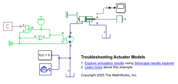
Troubleshoot Actuator Block Models
Troubleshoot problems in a model that contains actuator blocks and cannot converge during simulation. Blocks that interface with the mechanical domain, like actuators, can cause solver problems. These problems arise because the mechanical domain can introduce variables that cause a high differential index, which the solver cannot always overcome. A high differential index occurs when there are not sufficient degrees of freedom in the model. This behavior can cause issues where a model makes physical sense, but generates errors when the solver cannot converge.