M-Way N-Position Directional Valve (IL)

Libraries:
Simscape /
Fluids /
Isothermal Liquid /
Valves & Orifices /
Directional Control Valves
Description
The M-Way N-Position Directional Valve (IL) block represents a spool-operated directional valve with an arbitrary configuration of ports, spool positions, and orifices. The block accepts up to ten ports, ten spool positions, and 20 orifices. Valves with many configurations are most common in construction, agriculture, and some vehicle applications. This block simplifies complex parameterizations by allowing you to apply the same area characteristics to all flow paths. You can also individually specify the area characteristics for each flow path. You can parameterize the valve by specifying the opening area with tabulated or linear data or by using tabulated data that represents volumetric flow rate for a fully open orifice at varied pressure drops. The block uses a variable orifice to control the flow between a given pair of connected ports. The physical signal at port S triggers the spool motion to open or shut the valve. For more details about how the block calculates flow rate through a variable orifice, see Orifice (IL).
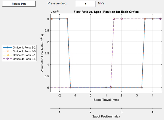
To generate a characteristic plot of the valve, click the Plot button next to Valve characteristics. To updated the plot after changing the block parameters, click the Reload Data button. You can control the shape of the characteristic plot. To select which lines are visible, click the appropriate orifice on the legend.
The default valve characteristic plot is:
The figure indicates locations A1, A2, B1, and B2.
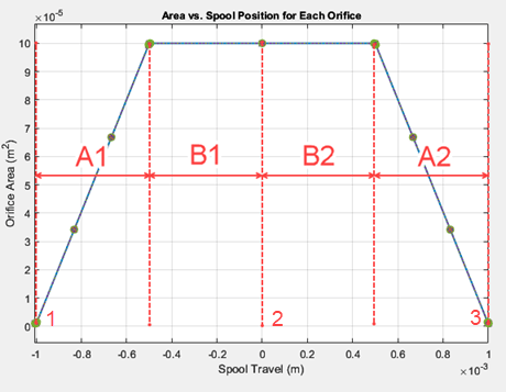
Position 1 is at spool travel of -1 mm. Position 2 is at spool travel of 0 mm, and Position
3 is at spool travel of 1 mm. Locations A1 and A2
represent the left- and right-side transition regions of the orifice opening area,
respectively. Locations B1 and B2 represent the
left- and right-side fully open regions of the orifice opening area, respectively. The
current spool position is the separation between B1 and
B2. When you set Area characteristics to
Identical for all flow paths.
A1 = (distance between spool positions 1 and 2) * (value of the Inter-position spool travel fraction for which orifices transition between open-closed parameter)
A2 = (distance between spool positions 2 and 3) * (value of the Inter-position spool travel fraction for which orifices transition between open-closed parameter)
B1 = (distance between spool positions 1 and 2) * (value of the Inter-position spool travel fraction for which orifices remain fully open parameter)
B2 = (distance between spool positions 2 and 3) * (value of the Inter-position spool travel fraction for which orifices remain fully open parameter)
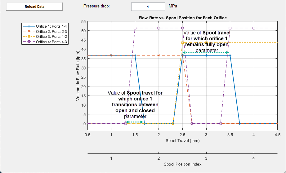
When you set Area characteristics to Different for each
flow path and Orifice parameterization to
Linear – Area vs. spool travel or Tabulated
data – Volumetric flow rate vs. pressure drop (linear with spool
travel):
A1 = A2 = value of the Spool travel for which orifice 2 transitions between open-closed parameter.
B1 = B2 = value of the Spool travel for which orifice 2 remains fully open parameter.
Orifice Parameterization
When you set Area parameterization to Different
for each flow path, you can parameterize each orifice by using the
parameters in the Orifice 1,…,20 sections. For example, if you
set Number of orifices to 3, the block includes sections for
Orifice 1, Orifice 2, and
Orifice 3. Each section has the same parameter names
followed by the number for that section.
The block icon updates automatically to indicate the orifice configuration, which you control with the appropriate Ports connected by orifice... parameter. If you connect one odd-numbered port to one even-numbered port, the block icon shows an arrow that points to the second listed port. The block icon indicates when a parameterization is invalid.
If you enable logging, the Orifice.S signal for each orifice
describes the spool position according to this table:
| Area characteristic parameter | ||
|---|---|---|
Identical for all flow paths | Different for each flow path | |
If Orifice parameterization is
Linear – Area vs. spool travel or
Tabulated data – Volumetric flow rate vs. pressure
drop (linear with spool travel) |
|
|
If Orifice parameterization is
Tabulated data – Area vs. spool
travel | Not a parameterization option |
In all other positions,
The orifice leakage area corresponds to the first and last elements of the extended spool travel vector. The orifice can have different leakage areas if the Vector of spool travel relative to discrete spool position for Orifice parameter has both a negative and positive region. |
Assumptions and Limitations
The block assumes that each orifice has a symmetric opening and closing about the spool position when you set Area characteristics to
Different for each flow path.The block assumes that each orifice has a symmetric opening and closing scaled with the spacing of the Spool travel at each spool position index parameter when you set Area characteristics to
Identical for all flow
							paths
.
Examples
Parameterize an M-Way N-Position Valve
Use a data sheet to parameterize an M-Way N-Position Valve (IL).

Front-Loader Actuation System
A simple actuation system that has a lift and tilt cylinder. Each cylinder is controlled by an open center, 6-way, 3-position directional valve. The valves are connected in series through their unloading branch such that the system pump unloads when both spool displacements are in neutral position. If either tilt or lift command applies, the unloading path closes.