Real-Time Simulation of Modular Multilevel Converter on FPGA
This example shows how to model a modular multilevel converter (MMC) with half-bridge power modules by using a generic switching-function modeling approach [1]. You can then generate HDL code and deploy onto a target hardware.
Set Up Synthesis Tool Path
To synthesize the generated HDL code, before you use HDL Coder™ to generate code, set up your synthesis tool path. For example, if your synthesis tool is Xilinx® Vivado®, install the latest version of Xilinx Vivado as shown in HDL Language Support and Supported Third-Party Tools and Hardware.
Then, set the tool path to the installed Xilinx Vivado executable by using the hdlsetuptoolpath function. For example, this command sets the synthesis tool path to point to your installed Vivado® Design Suite 2024.1 batch file:
hdlsetuptoolpath("ToolName","Xilinx Vivado",...
"ToolPath","C:\Xilinx\Vivado\2024.1\bin\vivado.bat")
Modular Multilevel Converter
A modular multilevel converter (MMC) is a type of power electronic converter used in high-voltage direct current (HVDC) transmission systems. The converter consists of multiple series-connected power modules. Each power module consists of one half-bridge and one capacitor on the DC side. To learn more, see Modular Multilevel Converter (Three-Phase) (Simscape Electrical).
Generalized Switching-Function Model of MMC
This example shows the topology of a three-phase MMC with five half-bridge power submodules in each arm. Each phase consists of two arms that are implemented with a number of series-connected power submodules. The converter is based on a switching-function model and can be generalized for N power submodules. The model is obtained by simplifying each arm of the converter to a controlled voltage source, an inductance, and a resistor. In the conventional modeling of an MMC, the arms are implemented with a number of series-connected power submodules. With the increase in number of power submodules, the complexity of the circuit increases. The generalization to MMC with N submodules becomes challenging due to a large number of state-space equations resulting in many time-variant matrices and differential equations to be solved.
In this implementation of a generic MMC switching-function model, the N serially connected power submodules per arm are replaced with an equivalent voltage source. This approach is faster and more computationally efficient than conventional models because it eliminates the matrix computations and reduces operations to simple integrations, multiplications, and additions. This is a hybrid plant implementation containing Simscape and Simulink blocks.
Open the model at the MATLAB® command prompt.
open_system("sschdlexMMCExample")
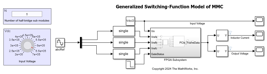
The configurations inside the FPGA Subsystem block run on an FPGA board and the components that are outside the FPGA Subsystem block run on a CPU in real time.
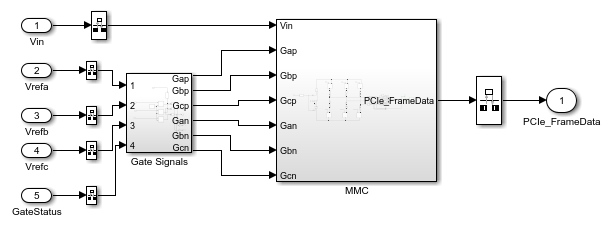
Open the FPGA Subsystem block that contains Simscape blocks.
open_system("sschdlexMMCExample/FPGA Subsystem")
Run Desktop Simulation
The input to the generalized switching-function based MMC model is an input voltage  set to 640 kV and can be changed from the input voltage Knob. The sample time of the Simscape model set to
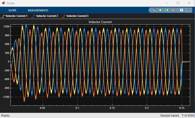
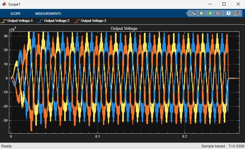
 1e-6 s. You can simulate the model and see the waveforms. The scopes provide the output voltage and inductor current waveforms. Alternatively, you can double-click the Data Logger on top of the output signals and open the Simulation Data Inspector.
Generate HDL Code and Synthesize the Results
To generate the HDL code, first generate an HDL implementation model from the Simscape™ model by using the Simscape HDL Workflow Advisor. For details, see Generate Optimized HDL Implementation Model from Simscape.
To open the Advisor, run the sschdladvisor function for the FPGA Subsystem block of your model.
sschdladvisor("sschdlexMMCExample/FPGA Subsystem")
In the Set target task, the fields are auto-populated. Synthesis Tool is specified as Xilinx Vivado, Family as KintexU, and Device as xcku115-flvb1760-1-c.
You can select the data type precision in the Generate implementation model task pane of the Simscape HDL Workflow Advisor. The generalized switching-function based MMC model is synthesized with Data type precision set to Fixed-point with Fixed-point word length set to 36-bit.
After the task passes in the Advisor, you see a link to the generated HDL implementation model. Generate HDL code for this HDL implementation model and synthesize the HDL code.
hdladvisor("gmStateSpaceHDL_sschdlexMMCExample_fixpt/FPGA Subsystem")
Before you generate HDL code, in the HDL Workflow Advisor, in the Set Target Frequency task, specify Target Frequency as 79. HDL Coder synthesizes the HDL code on the target platform and generates area and timing reports for your design based on the target device that you specify. You can run logic synthesis for a specified FPGA device and get the synthesis reports. For details about the HDL code generation and synthesis of code, see Generate FPGA Bitstream for Two-Phase DC-DC Converter with Tunable Run-Time Parameters.

The model is configured to run on the FPGA at a sampling frequency of 1 MHz (corresponding to a sample time of 1 μs, as set on Solver Configuration block of the Simscape model). The model uses native floating-point operators, which introduce a latency of 79 cycles. To compensate for this latency, the value of oversampling factor is automatically set to 79 so that the model runs at a faster clock rate.
The FPGA clock frequency (or Target Frequency specified in the HDL Code Generation > Target > Objectives Settings section of the Configuration Parameters dialog box) is defined as:
FPGA clock frequency = Sampling frequency × (Oversampling factor × Number of solver iterations)
For the MMC model, the required FPGA clock frequency is:
1 MHz × (79 × 1) = 79 MHz
Here, the oversampling factor is 79, and the number of solver iterations is 1.
The synthesis results show that the maximum achievable FPGA clock frequency is 104.21 MHz. However, the required target frequency is set to 79 MHz to ensure that the model runs at a sampling frequency of 1 MHz on the FPGA. To learn more about different parameters, see Troubleshooting Real-Time Hardware Deployment Issues in Simscape Hardware-in-the-Loop Workflow.
References
[1] Adam, G. P., P. Li, I. A. Gowaid, and B. W. Williams. “Generalized switching function model of modular multilevel converter.” 2015 IEEE International Conference on Industrial Technology (ICIT) 2015: 2702–2707. https://doi.org/10.1109/ICIT.2015.7125496.
See Also
sschdladvisor | hdladvisor | Modular Multilevel Converter
Arm (Simscape Electrical) | Modular Multilevel Converter
(Three-Phase) (Simscape Electrical)