Generate FPGA Bitstream for Two-Phase DC-DC Converter with Tunable Run-Time Parameters
This example shows how to generate FPGA bitstream for a Simscape™ model and tune the Simscape run-time parameters without rerunning the synthesis.
Simscape Model with Tunable Run-Time Parameters
In this example, you learn how you can generate FPGA bitstream for Simscape two-phase interleaved bidirectional DC-DC converter model with tunable run-time parameters. First, you generate an HDL implementation model from a Simscape two-phase DC-DC converter model by using the Simscape HDL Workflow Advisor. Then, for this implementation model, you generate the HDL code and synthesize the results by using the guided steps in the HDL Workflow Advisor. For more information, see HDL Workflow Advisor Tasks. You can tune the run-time parameter values for the Simscape model without rerunning the synthesis.
The parameter tuning supports:
Linear time-invariant models with local solver set to
Backward EulerorTrapezoidal RuleSingledata type precision
Set Up Synthesis Tool Path
To synthesize the generated HDL code, before you use HDL Coder™ to generate code, set up your synthesis tool path. For example, if your synthesis tool is Xilinx® Vivado®, install the latest version of Xilinx Vivado as shown in HDL Language Support and Supported Third-Party Tools and Hardware.
Then, set the tool path to the installed Xilinx Vivado executable by using the hdlsetuptoolpath function. For example, this command sets the synthesis tool path to point to your installed Vivado® Design Suite 2024.1 batch file:
hdlsetuptoolpath("ToolName","Xilinx Vivado",...
"ToolPath","C:\Xilinx\Vivado\2024.1\bin\vivado.bat")
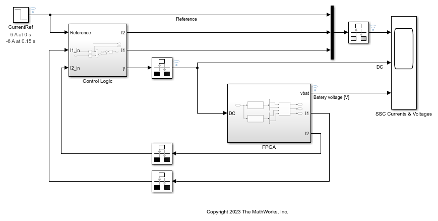
Two-Phase DC-DC Converter Current Control Model
The two-phase converter comprises two Bidirectional DC-DC Converters with ideal IGBTs. These configurations are a part of Simscape network inside the FPGA subsystem. To adjust the duty cycle, the Control Logic subsystem uses a PI-based control algorithm. To reduce the ripple at the output port of the converter, the two phases are switched with the same duty ratio but with a relative phase shift of 180 degrees. The SSC Currents and Voltages subsystem contains scopes that allow you to see the simulation results.
Open the model in the MATLAB® Command Window.
open_system("sschdlexTwoPhaseDCDCConverterExample")
To see the waveforms, simulate the model.
sim("sschdlexTwoPhaseDCDCConverterExample")
open_system("sschdlexTwoPhaseDCDCConverterExample/SSC Currents and Voltages")

Set Up Tunable Parameters
You can set up a model for parameter tuning in two different ways.
Make Simscape run-time parameters run-time configurable — To specify a Simscape block parameter as run-time configurable, change the Configurability setting in the block property inspector underneath the parameter name, from
Compile-timetoRun-time. For more information on enabling run-time configurability, see About Simscape Run-Time Parameters (Simscape).
Use the
sschdl.generateOptimizedModelfunction — Thesschdl.generateOptimizedModelfunction generates an optimized model for FPGA deployment by replacing the Simscape switches with their dynamic equivalents from theDynamic Switch Library. For the blocks in this library, the run-time configurability is not a mask parameter. You can set any mask parameter to be aSimulink.Parameterobject by settingobj.CoderInfo.StorageClassequal to"ExportedGlobal". For more information, see Generate DUT Ports for Tunable Parameters. This setup enables parameter tuning for the corresponding parameter. In the model, navigate toFPGA>Simscape Network>Bidirectional DC-DC Convertersubsystem and double-click the Switch block. Here,Gsandsare Simscape run-time parameters (orSimulink.Parameterobjects) defined in thePreLoadFcnmodel callback in the Model callback pane on the Callbacks tab when you select Model Settings > Model Properties on the Modeling tab.
Once you set up the tunable parameter settings in the model, save the model for generating HDL implementation model from it.
Generate HDL Implementation Model
The Simscape HDL Workflow Advisor converts the Simscape plant model to an HDL-compatible implementation model from which you generate HDL code. To generate the HDL implementation model:
1. Open the Simscape HDL Workflow Advisor.
sschdladvisor("sschdlexTwoPhaseDCDCConverterExample/FPGA")
2. For each task, right-click and select Run This Task. In the Extract discrete equations, the right pane displays a table for all tunable parameters.
3. In the Implementation model generation task folder, right-click the Generate implementation model task and select Run to Selected Task.
After the task passes, you see a link to the HDL implementation model gmStateSpaceHDL_sschdlexTwoPhaseDCDC.
Generate HDL Code from Implementation Model
To modify the configuration parameter values for HDL code generation, run this command:
hdlsetup("gmStateSpaceHDL_sschdlexTwoPhaseDCDC")
Open HDL Workflow Advisor
The HDL Workflow Advisor guides you through the tasks required for generating HDL code and an FPGA design process. It provides you with feedback on the results of each task. When you complete the tasks, you have a synthesis result report from one of the supported synthesis tools.
To open the FPGA subsystem in the HDL implementation model into the HDL Workflow Advisor, run this command:
hdladvisor("gmStateSpaceHDL_sschdlexTwoPhaseDCDC/FPGA")
You can also open the HDL Workflow Advisor from your model window. Right-click the FPGA subsystem and select HDL Workflow Advisor.
Set Target Device and Synthesis Tool
Before you generate HDL code, if you want to deploy the code onto a target platform, specify the synthesis tool.
Open the HDL Workflow Advisor.
Under the Set Target task folder, in the Set Target Device and Synthesis Tool task, specify Target workflow as
Generic ASIC/FPGAand Synthesis tool asXilinx Vivado. The rest of the fields are auto-populated. Specify the Family asKintex7, Device asxc7k325t, Package asfbg676, and Speed as-1.In the Set Target Frequency task, the Target Frequency is automatically set to 140.
Select the task that you want to run and click Run This Task.
Generate HDL Code
To generate HDL code, run the tasks under the HDL Code Generation task folder.
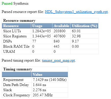
Synthesize Generated HDL Code
HDL Coder synthesizes the HDL code on the target platform and generates area and timing reports for your design based on the target device that you specify. You can run logic synthesis for a specified FPGA device and get the synthesis reports.
In the FPGA Synthesis and Analysis task folder:
Create an FPGA synthesis project for your supported FPGA synthesis tool.
Start supported FPGA synthesis tools to perform synthesis, mapping, and place/route tasks. To run FPGA synthesis, right-click the Run Synthesis task under the Perform Synthesis and P/R subtask folder. This starts Xilinx Vivado and executes the Vivado Synthesis step. You can annotate your original model with critical path information obtained from the synthesis tools.
Tune Run-Time Parameters
You can update the run-time parameter values of the generated HDL implementation model and fine-tune it. To generate and update tunable parameter data file for the implementation model:
1. Reopen the original Simscape model and update the parameter values to the desired configuration.
2. In MATLAB Command Window, run the sschdl.updateRuntimeParameters function:
sschdl.updateRuntimeParameters("sschdlexTwoPhaseDCDCConverterExample",...
"sschdl\sschdlexTwoPhaseDCDCConverterExample\stateSpaceParameters",...
"sschdl\sschdlexTwoPhaseDCDCConverterExample\tunableParameters","myTunableParams");
This generates a new data file with the specified name myTunableParams.mat in the generated sschdl folder, which contains the new state-space parameters with updated tunable values. Use this file in place of the tunableParameters.mat file to update your Simulink® or Simulink Real-Time™ (SLRT) interface model parameter values. To update the files in the Simulink or SLRT interface model, open the Simulink or SLRT interface model. On the Modeling tab, select Model Settings > Model Properties. On the Callbacks tab, in the Model callback pane, select InitFcn and replace the load command for the tunableParameters.mat file with the newly generated myTunableParams.mat file.
Deploy Two-Phase DC-DC Converter to Speedgoat FPGA I/O Modules
Generate FPGA Bitstream for Speedgoat Target Computer
1. Open the HDL implementation model, and then open the HDL Workflow Advisor for the implementation model.
open_system("gmStateSpaceHDL_sschdlexTwoPhaseDCDC")
To open the HDL Workflow Advisor for a subsystem inside the model, use the hdladvisor function.
hdladvisor("gmStateSpaceHDL_sschdlexTwoPhaseDCDC/FPGA")
2. In the Set Target Device and Synthesis Tool task, specify Target workflow as Simulink Real-Time FPGA I/O and Target platform as Speedgoat IO334-325K.
3. In the Set Target Reference Design task, select a value of X4 for the parameter PCIe lanes, and click the Run This Task button.
4. In Set Target Interface task, map the input and output single data type ports to PCIe Interface and click the Run This Task button.

5. In the Set Target Frequency task, the default value of Target Frequency (MHz) is set to 100. For this example model, this value is 140.
6. Right-click the Generate Simulink Real-Time Interface task, and select Run to Selected Task to generate the HDL IP core and FPGA bitstream.
Deploy Bitstream to Speedgoat IO334-325k Target
The FPGA subsystem is automatically replaced in the real-time interface model with Speedgoat® driver blocks to initialize the hardware and to interface with the FPGA during run time.
Connect to Target Machine and Run Real-Time Simulation
The model can now be deployed onto the Speedgoat real-time target machine. Make sure that the Speedgoat real-time target machine is connected to the host computer and powered on.
You download the bitstream by using the Simulink Real-Time Explorer. To open the Simulink Real-Time Explorer, enter the command slrtExplorer. Alternatively, you can open the Explorer from the Real-Time tab of the Simulink Toolstrip.
The Simulink Editor displays the Real-Time tab for models that are configured for the speedgoat.tlc code generation target. Click the Connect to Target Computer button in the Simulink Real-Time tab to connect to the machine. Once connected, click the Run on Target button to deploy the model.
Simulink Real-Time automatically generates C code from your model by using Simulink Coder™. The generated code and the bitstream for the FPGA are loaded onto the target machine, and model execution starts automatically.
See Also
sschdladvisor | hdladvisor | hdlsetup | sschdl.updateRuntimeParameters | sschdl.generateOptimizedModel
Topics
- Generate and Validate HDL Code for Simscape Model
- FPGA-Based HIL Deployment of Simscape Model on Speedgoat FPGA I/O Module
- Deploy Simscape DC Motor Model to Speedgoat FPGA IO Module
- Generate HDL Code for Simscape Three-Phase PMSM Drive Containing Averaged Switch
- Simulate Large Time Steps Using Trapezoidal Rule Solver for Real-Time FPGA Deployment
- Generate HDL Code for Simscape Models by Using Dynamic Switch Approximation