Generate and Validate HDL Code for Simscape Model
R2026bThis example shows how to generate HDL code for a Simscape™ half-wave rectifier model. By using the Simscape HDL Workflow Advisor, you can generate an HDL implementation model and validate its functionality. You can then generate HDL code from the implementation model.
To learn more about Simscape Hardware-in-the-Loop workflow, see Get Started with Simscape Hardware-in-the-Loop Workflow.
The Half-Wave Rectifier Model
This example uses a Simscape half-wave rectifier model to generate HDL code.
Open the model at the MATLAB® command prompt.
open_system("sschdlexHalfWaveRectifierExample")
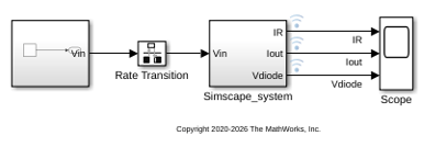
At the top level, the model contains a Simscape_system subsystem block that implements the half-wave rectifier algorithm. A Sine Wave block provides the input signal and a Rate Transition block discretizes the continuous time input signal. A Scope block is connected to the Simscape network to observe the output. Open the Simscape_system subsystem to view the half-wave rectifier algorithm.
open_system("sschdlexHalfWaveRectifierExample/Simscape_system")
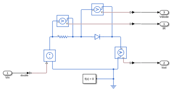
The half-wave rectifier consists of a resistor (linear block) and a diode (switched linear block). The Simscape network and the solver settings are preconfigured for HDL compatibility. At the input and output port interfaces, the model uses Simulink-PS Converter and PS-Simulink Converter blocks to connect Simulink signals with the Simscape physical network. If you open the Block Parameters dialog box for the Solver Configuration block, Use local solver is selected and Backward Euler is specified as the Solver type. For more information on configuring a Simscape model for HDL compatibility, see Get Started with Simscape Hardware-in-the-Loop Workflow.
To observe the model behavior, simulate the model and open the Scope block.
sim("sschdlexHalfWaveRectifierExample")
open_system("sschdlexHalfWaveRectifierExample/Scope")
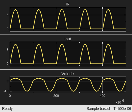
The output waveform shows the rectified signal produced by the diode.
Generate HDL Implementation Model
To generate an HDL implementation model from the Simscape algorithm and to set up validation logic:
1. Open the Simscape HDL Workflow Advisor for the Simscape network of the model, Simscape_system.
sschdladvisor("sschdlexHalfWaveRectifierExample/Simscape_system")
This command updates the Model Advisor cache and opens the Simscape HDL Workflow Advisor.
2. The Advisor guides you through the steps required to convert your Simscape network to an HDL-compatible state-space representation. For each task, right-click the task and select Run This Task. To learn more about the Simscape HDL Workflow Advisor tasks, right-click that folder or task and select What's This?. For more information about each task, see Simscape HDL Workflow Advisor Tasks.
3. Under the Implementation model generation task folder, in the Generate implementation model task pane, select Generate validation logic for the implementation model and set the value of Validation logic tolerance to 0.001.
4. Right-click the Generate implementation model task and select Run to Selected Task.
After the task passes, you see links to the HDL implementation model and a state-space validation model. The implementation model has the same name as the original Simscape model with the prefix gmStateSpaceHDL_. The state-space validation model has the same name as the implementation model with the suffix _vnl.
Open and Examine HDL Implementation Model
In the Generate implementation model task pane, click the link to open the implementation model. The model contains a Simscape_system subsystem that contains an HDL Subsystem block. The HDL Subsystem block models the state-space representation that you generated from the Simscape model.
Alternatively, enter these commands to open the model and the subsystem block.
open_system("gmStateSpaceHDL_sschdlexHalfWaveRect")
open_system("gmStateSpaceHDL_sschdlexHalfWaveRect/Simscape_system")
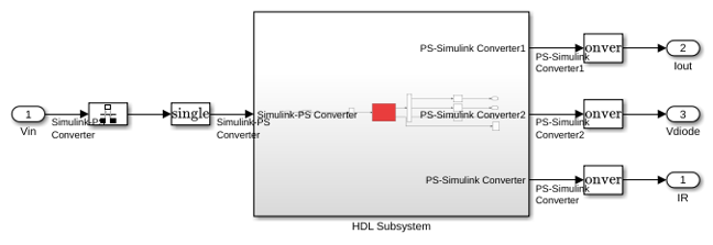
The ports of this subsystem use the same name as the Simulink-PS Converter and PS-Simulink Converter blocks in your original Simscape model. If you navigate inside this subsystem, you see several delays, adders, and update blocks that model the state-space equations.
open_system("gmStateSpaceHDL_sschdlexHalfWaveRect/Simscape_system/HDL Subsystem/HDL Algorithm")
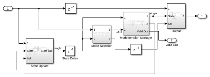
Simulate the HDL implementation model and open the Scope block to view the results.
sim("gmStateSpaceHDL_sschdlexHalfWaveRect")
open_system("gmStateSpaceHDL_sschdlexHalfWaveRect/Scope")
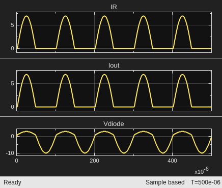
HDL code is generated for the HDL Subsystem block inside this model.
Validate HDL Algorithm
To verify that the HDL implementation model produces results consistent with the original Simscape algorithm, open and simulate the validation model.
open_system("gmStateSpaceHDL_sschdlexHalfWaveRect_vnl")
sim("gmStateSpaceHDL_sschdlexHalfWaveRect_vnl")
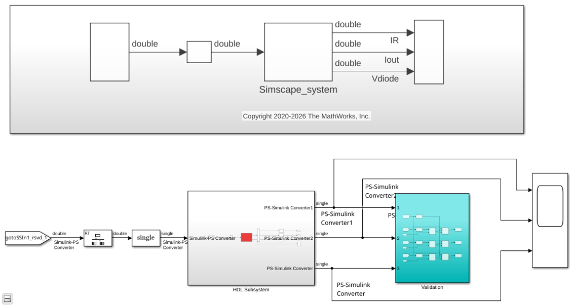
The output of this model matches the original Simscape model. The simulation does not generate assertions, which indicates that the outputs match. For more information on validation workflows, see Validate HDL Implementation Model to Simscape Algorithm.
Generate HDL Code and Validation Model
The implementation model uses single-precision data type and generates HDL code in Native Floating Point mode. Floating-point operators can introduce delays. Because the design contains feedback loops, to allocate sufficient delays for the operators inside the feedback loops, the model uses clock-rate pipelining.
For more information, see:
Before you generate HDL code, enable validation model generation. The validation model compares the output of the generated model and the original model. To learn more, see Generated Model and Validation Model.
To generate the validation model, enter these commands.
HDLmodelname = "gmStateSpaceHDL_sschdlexHalfWaveRect";
hdlset_param(HDLmodelname, "GenerateValidationModel", "on");
To generate HDL code, enter this command.
makehdl("gmStateSpaceHDL_sschdlexHalfWaveRect/Simscape_system/HDL Subsystem");
The generated HDL code and validation model are saved in the hdlsrc folder. The generated code is saved as HDL_Subsystem.vhd. To open the validation model, click the link to gm_gmStateSpaceHDL_sschdlexHalfWaveRect_vnl.slx in the code generation logs in the Command Window.
The validation model allows you to compare outputs graphically. The scope shows graphs of the signals IR, Iout, and Vdiode. The first graph shows the output of the generated model, and the middle graph shows the output of the implementation model. The bottom graph shows the difference between outputs of both models. The outputs match, so the error is zero.

