Lane-Keeping System for Self-Driving Trucks
This example shows how to design a lane-keeping system (LKS) with longitudinal and lateral controls for self-driving trucks in Simulink® and simulate it with RoadRunner Scenario.
Introduction
RoadRunner Scenario is an interactive editor that enables you to design scenarios for simulating and testing automated driving systems. You can place vehicles, define their paths and interactions in the scenario, and then simulate the scenario in the editor. RoadRunner Scenario supports in-editor playback for scenario visualization and connecting to other simulators, such as MATLAB® and Simulink, for cosimulation.
A truck lane-keeping system steers a truck to travel within its lanes. It also maintains a set velocity, or a safe distance from a preceding vehicle in the same lane. This example designs a lane-keeping system for trucks using probabilistic vision and radar sensors. It uses vision sensors to detect lanes and vehicles, then fuses the vehicle detections with detections from a radar sensor to improve the robustness of its perception. The controller uses the lane detections, vehicle detections, and set speed to control steering and acceleration. The example also shows how to integrate a lane-following controller with tractor-trailer dynamics.
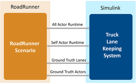
This figure shows an overview of the information exchanged between RoadRunner Scenario and the truck lane-keeping test bench model in Simulink. The truck lane-keeping model reads all other actor runtimes and the self-actor runtime from RoadRunner Scenario. RoadRunner Scenario also provides the ground truths of lane boundaries and actor information to Simulink. Using this information, probabilistic sensors provide vision and radar detections. The model controls the ego vehicle using these detections and writes back the updated ego pose to RoadRunner Scenario.
In this example, you:
Set Up Environment — Configure MATLAB settings to interact with RoadRunner Scenario.
Explore RoadRunner Scenario — Explore the RoadRunner scene and scenario used to simulate the lane-keeping system.
Explore Test Bench Model — Explore the test bench model, which contains an interface for RoadRunner Scenario, the lane-keeping system, and a metrics assessment subsystem that assesses model performance using ground truth data.
Explore Algorithm Models — Explore algorithm models that implement the sensor fusion, decision logic, and controller components to build the lane-keeping application.
Simulate Scenario — Cosimulate the lane-keeping scenario with RoadRunner Scenario, and inspect the longitudinal and lateral performance.
Explore Other Scenarios — Test the system in other scenarios under additional conditions.
This example requires the Automated Driving Toolbox™ Interface for Unreal Engine 4 Projects support package. For more information on downloading and installing support packages, see Get and Manage Add-Ons.
pathToRRScene = fullfile(matlabshared.supportpkg.getSupportPackageRoot, ...
    "toolbox","shared","sim3dprojects","spkg", ...
    "roadrunner","RoadRunnerProject","Scenes","CurvedRoad.rrscene");
pathToAssets = fullfile(matlabshared.supportpkg.getSupportPackageRoot, ...
    "toolbox","shared","sim3dprojects","spkg", ...
    "roadrunner","RoadRunnerProject","Assets","Markings","*.rrmeta");

if (~exist(pathToRRScene,"file"))
    error("This example requires you to download and install Automated Driving Toolbox Interface for Unreal Engine 4 Projects support package")
end
Set Up Environment
This section shows how to set up the environment to cosimulate the lane-keeping system.
Specify the path to your local RoadRunner installation folder. This code shows the path for the default installation location on Windows®.
rrAppPath = "C:\Program Files\RoadRunner " + matlabRelease.Release + "\bin\win64";
Specify the path to your RoadRunner project. This code shows the path to a sample project folder on Windows.
rrProjectPath = "C:\RR\MyProjects";
To update the path for the RoadRunner installation folder, get the root object within the settings hierarchical tree. For more information, see SettingsGroup.
s = settings;
s.roadrunner.application.InstallationFolder.TemporaryValue = rrAppPath;
Open RoadRunner using the specified path to your project.
rrApp = roadrunner(rrProjectPath);
The rrApp RoadRunner object enables you to interact with RoadRunner from the MATLAB workspace. You can open the scenario and update scenario variables using this object. For more information on this object, see roadrunner.
To explore the test bench model, load the Truck Lane-Keeping System project.
openProject("TruckLaneKeepingSystem");
Copy the RoadRunner scene, scenario, and behavior files to the RoadRunner project.
TruckLaneKeepingSystemProject = currentProject;
projectPath = convertStringsToChars(TruckLaneKeepingSystemProject.RootFolder);
projectRootFolder = projectPath(1:find(projectPath=='\',1,'last')-1);

copyfile(pathToRRScene,fullfile(rrProjectPath,"Scenes"),"f")
copyfile(pathToAssets, fullfile(rrProjectPath,"Assets/Markings"),"f")
copyfile(fullfile(projectRootFolder,"TruckLKSTestScenarios/Scenarios"), ...
    fullfile(rrProjectPath,"Scenarios"),"f")
copyfile(fullfile(projectRootFolder, ...
    "TruckLaneKeepingSystem/TestBench/TruckLKS.rrbehavior.rrmeta"), ...
    fullfile(rrProjectPath,"Assets","Behaviors"),"f")
copyfile(fullfile(projectRootFolder, ...
    "TruckLKSTestScenarios/Vehicles/TrailerLoad.rrvehicle.rrmeta"), ...
    fullfile(rrProjectPath,"Assets","Vehicles"),"f")
Explore RoadRunner Scenario
This example uses the CurvedRoad.rrscene scene to simulate the lane-keeping model. The scene contains a two-way, four-lane, curved highway road. Open the scene.
openScene(rrApp,"CurvedRoad.rrscene")
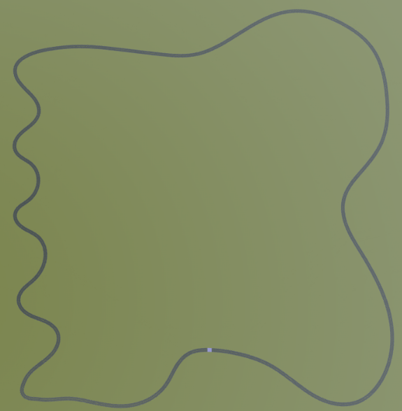
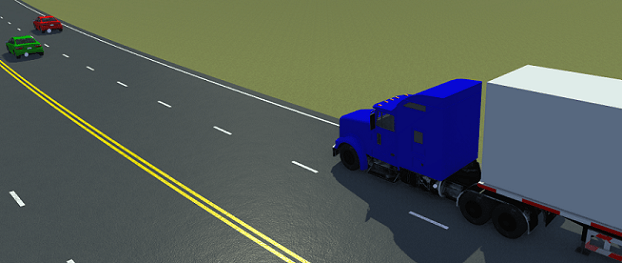
scenario_TruckLKS_01_Curve_StopnGo.rrscenario file is a RoadRunner scenario compatible with the TruckLKSTestBench model. This is an open-loop scenario containing the ego vehicle and multiple target vehicles on a curved road.
In this scenario, a lead vehicle slows down in front of the ego vehicle while other vehicles travel in adjacent lanes. Open the scenario.
openScenario(rrApp,"scenario_TruckLKS_01_Curve_StopnGo.rrscenario")
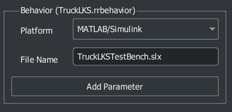
To simulate lane-keeping behavior for the ego vehicle, specify custom behavior for it using the TruckLKS.rrbehavior.rrmeta file.
Connect to the RoadRunner Scenario server for cosimulation using the createSimulation function and enable data logging.
rrSim = createSimulation(rrApp);
set(rrSim,Logging="on");
Connection status: 1
Connected to RoadRunner Scenario server on localhost:62312, with client id {c68c2159-cc51-484d-b8db-7ccb42b6ba0a}
rrSim is a ScenarioSimulation object. Use this object to set variables and to read scenario and map-related information.
The lane-keeping application is designed to run at a step size of 0.05 seconds. Set the simulation step size of RoadRunner Scenario.
Ts = 0.05;
set(rrSim,StepSize=Ts)
Partition Algorithm and Test Bench
The model is partitioned into separate algorithm and test bench models:
Algorithm models — Algorithm models are reference models that implement the functionality of individual components.
Test bench model — The Truck LKS test bench specifies the stimulus and environment to test the algorithm models.
Explore Test Bench Model
In this example, you use a system-level simulation test bench model to simulate and test the behavior of the lane-keeping model with RoadRunner Scenario. Open the test bench model.
open_system("TruckLKSTestBench")

The test bench model contains RoadRunner Scenario blocks, which configure, read from, and write to RoadRunner Scenario the actor runtimes and the ground truth actor and lane information. It also contains these modules:
Sensors— Subsystem that specifies the vision and radar probabilistic sensors used for simulation with RoadRunner Scenario.Compute Longitudinal Velocity— Subsystem that computes the longitudinal speed of the ego vehicle based on the actor runtime from RoadRunner.Forward Vehicle Sensor Fusion— Algorithm model that fuses vehicle detections from the vision and radar sensors.Lane Following Decision Logic— Algorithm model that specifies the lateral and longitudinal decision logic and provides information related to the most important object (MIO) and lane center to the controller.Truck Lane Following Controller— Algorithm model that specifies steering angle and acceleration controls.6DOF Vehicle Dynamics— Subsystem that implements a model of a three-axle tractor towing a three-axle trailer through a hitch.Pack Actor Poses— Subsystem that packs the output from the vehicle dynamics model into the format that RoadRunner requires.Metrics Assessment— Subsystem that assesses system-level behaviors.
The Forward Vehicle Sensor Fusion, Lane Following Decision Logic, and Metrics Assessment subsystems are based on the subsystems used in the Highway Lane Following example. The 6DOF Vehicle Dynamics model is based on Truck Platooning with RoadRunner Scenario example.
RoadRunner Scenario Blocks
The RoadRunner Scenario blocks consist of:
RoadRunner Scenario— Defines the interface for an actor model.Vision Info— RoadRunner Scenario Reader block that reads the ground truth actors and lane boundary information for the probabilistic vision sensor.Radar Info— RoadRunner Scenario Reader block that reads the ground truth actors for the probabilistic radar sensor.Ego— RoadRunner Scenario Reader block that reads the ego pose of the modeled vehicle.Tractor Runtime— RoadRunner Scenario Writer block that writes the updated tractor pose back to RoadRunner Scenario.Trailer Runtime— RoadRunner Scenario Writer block that writes the updated trailer pose back to RoadRunner Scenario.
Sensors Subsystem
The Sensors subsystem synthesizes the vision and radar sensors, which are attached to the ego vehicle.
Open the Sensors subsystem.
open_system("TruckLKSTestBench/Sensors")
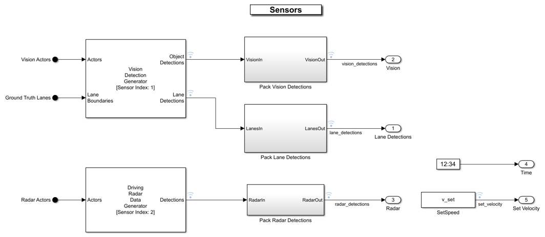
The Sensors subsystem contains these blocks:
The Vision Detection Generator block generates vehicle and lane detections from a camera mounted on the ego vehicle.
The Driving Radar Data Generator block generates detections from a radar sensor mounted on the ego vehicle.
The
Pack Vision Detectionsblock packs the object detection output of the Vision Detection Generator.The
Pack Lane Detectionsblock packs the lane detection output of the Vision Detection Generator.The
Pack Radar Detectionsblock packs the output of the Driving Radar Data Generator.
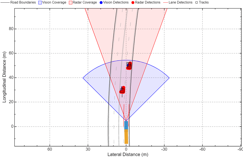
The vision and the radar sensors are placed at the front of the truck with an offset from the ground. The Bird's-Eye Scope displays sensor coverage by using a cuboid representation. The radar coverage area and detections are in red. The vision coverage area and detections are in blue.
Vehicle Dynamics
The 6DOF Vehicle Dynamics subsystem models a tractor, trailer, and hitch with six degrees of freedom (DOF). Open the 6DOF Vehicle Dynamics subsystem.
open_system("TractorTrailer6DOF")

The vehicle dynamics model has three subsystems, for the tractor, the trailer, and the hitch. Both the three-axle tractor and three-axle trailer subsystems include models for the wheels, suspension, and vehicle body. The vehicle dynamics model accepts acceleration and steering as input and outputs information about the vehicle body, wheels, and suspension. The model converts the input acceleration into the axle torque and brake pressure of the tractor. The steering controls the steering angle of the front axle of the tractor.
For more details about the vehicle dynamics model, see the Three-Axle Tractor Towing a Three-Axle Trailer (Vehicle Dynamics Blockset) example.
Metrics Assessment
The Metrics Assessment subsystem enables system-level metric evaluations using the ground truth information from the scenario.
Open the Metrics Assessment subsystem.
open_system("TruckLKSTestBench/Metrics Assessment")
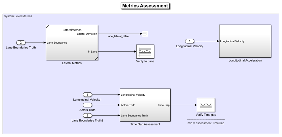
Using this subsystem, you can evaluate the system-level behavior using these metrics:
Verify In Lane— This block verifies that the ego vehicle is following one of the lanes on the road throughout the simulation.Verify Time Gap— This block verifies that the time gap between the ego vehicle and the lead vehicle is more than 1.5 seconds. The time gap between the two vehicles is defined as the ratio of the calculated headway distance to the ego vehicle velocity.
This subsystem also logs the information required to plot the lateral and longitudinal results.
Explore Algorithm Models
The lane-keeping system in this example works by integrating the forward vehicle sensor fusion, lane-following decision logic, and truck lane-following controller components.
The forward vehicle sensor fusion component fuses vehicle and radar detections from the sensors and tracks the detected vehicles using the central level tracking method.
Open the Forward Vehicle Sensor Fusion algorithm model.
open_system("ForwardVehicleSensorFusion")

The forward vehicle sensor fusion model reads vehicle detections from vision and radar sensors. The model clusters radar detections and concatenates radar detections with vision detections. Then, the model tracks the clustered vehicle detections using a joint probabilistic data association (JPDA) tracker. For more details on forward vehicle sensor fusion, see Forward Vehicle Sensor Fusion.
The lane-following decision logic algorithm model specifies lateral and longitudinal decisions based on the detected lanes and tracks.
Open the Lane Following Decision Logic algorithm model.
open_system("LaneFollowingDecisionLogic")
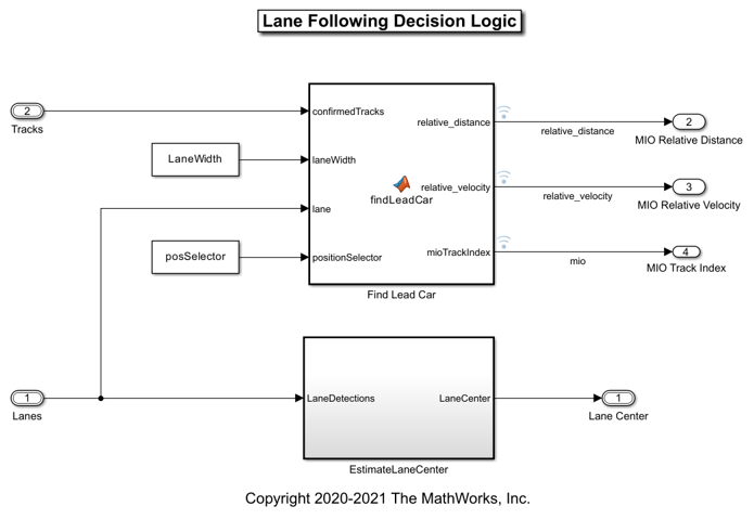
The lane-following decision logic model takes the detected lanes from the Vision Detection Generator block and the confirmed tracks from the forward vehicle sensor fusion module as inputs. It estimates the lane center and also determines the MIO lead car traveling in the same lane as the ego vehicle. It outputs the relative distance and relative velocity between the MIO and ego vehicle.
The truck lane-following controller specifies the longitudinal and lateral controls.
Open the Truck Lane Following Controller algorithm model.
open_system("TruckLaneFollowingController")
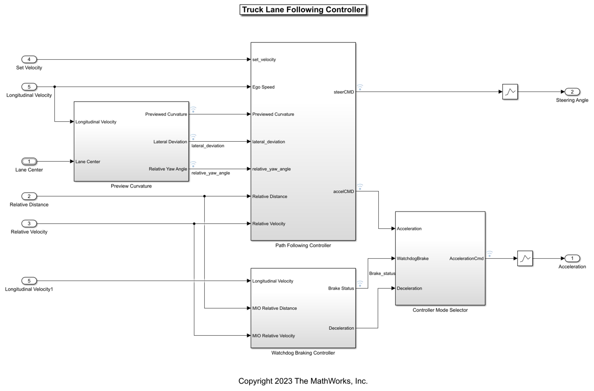
The controller takes the set velocity, lane center, and MIO information as inputs. It uses a path-following controller to control the steering angle and acceleration for the ego vehicle. It also uses a watchdog braking controller to apply brakes as a fail-safe mode. The controller outputs the steering angle and acceleration command that determines whether to accelerate, decelerate, or apply brakes. The Vehicle Dynamics block uses these outputs for lateral and longitudinal control of the ego vehicle.
Simulate Scenario
Disable the MPC update messages.
mpcverbosity("off");
This example uses the helperSLTruckLaneKeepingSystemSetup helper function to set up the ego and target actor profiles along with the sensor parameters. These values are scenario dependent, and can change based on the selected scenario.
helperSLTruckLaneKeepingSystemSetup(rrApp,rrSim,scenarioFileName="scenario_TruckLKS_01_Curve_StopnGo")
This model can take a couple of minutes to update the diagram when you compile it for the first time. Update the model before running the simulation.
set_param("TruckLKSTestBench",SimulationCommand="update")
Simulate the scenario, and observe how the ego vehicle stays in the current lane and adjusts its speed to avoid collision with the lead vehicle.
set(rrSim,SimulationCommand="Start")
while strcmp(get(rrSim,"SimulationStatus"),"Running")
   pause(1)
end
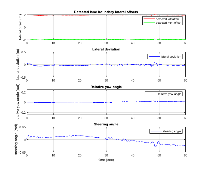
Plot the lateral controller performance results.
hFigLatResults = helperPlotLFLateralResults(logsout);
Close the figure.
close(hFigLatResults)
Examine the simulation results.
The Detected lane boundary lateral offsets plot shows the lateral offsets of the detected left-lane and right-lane boundaries from the centerline of the lane. The detected values are close to the ground truth of the lane, but deviate by small quantities.
The Lateral deviation plot shows the lateral deviation of the ego vehicle from the centerline of the lane. Ideally, lateral deviation is 0 meters, which implies that the ego vehicle follows the centerline exactly. Small deviations occur when the vehicle changes velocity to avoid collision with another vehicle.
The Relative yaw angle plot shows the relative yaw angle between the ego vehicle and the centerline of the lane. The relative yaw angle is very close to 0 radians, which implies that the heading angle of the ego vehicle matches the yaw angle of the centerline closely.
The Steering angle plot shows the steering angle of the ego vehicle.
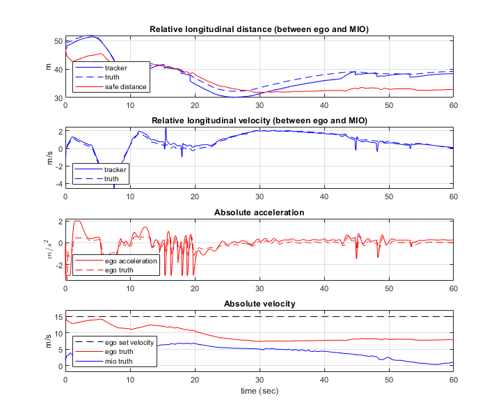
Plot the longitudinal controller performance results.
hFigLongResults = helperPlotLFLongitudinalResults(logsout,time_gap,default_spacing);
Close the figure.
close(hFigLongResults)
Examine the simulation results.
The Relative longitudinal distance plot shows the distance between the ego vehicle and the MIO. In this case, the ego vehicle approaches the MIO and gets close to it, or exceeds the safe distance in some cases.
The Relative longitudinal velocity plot shows the relative velocity between the ego vehicle and the MIO. In this example, the vehicle detector detects only positions, so the tracker in the control algorithm estimates the velocity. The estimated velocity is less than the actual (ground truth) MIO relative velocity.
The Absolute acceleration plot shows that the controller commands the vehicle to decelerate when it gets too close to the MIO.
The Absolute velocity plot shows that the ego vehicle initially follows the set velocity, but when the MIO slows down, the ego vehicle also slows down to avoid a collision.
Explore Other Scenarios
In this example, you have explored the behavior for the scenario_TruckLKS_01_Curve_StopnGo.rrscenario scenario, which uses the CurvedRoad.rrscene scene. You can use the same test bench model to explore other scenarios. This example provides these additional scenarios that are compatible with the TruckLKSTestBench model.
scenario_TruckLKS_02_Curve_AutoRetarget.rrscenarioscenario_TruckLKS_03_Curve_CutInOut.rrscenario
You can explore these scenarios in RoadRunner. For example, to open the scenario_TruckLKS_02_Curve_AutoRetarget.rrscenario scenario, enter this command.
openScenario(rrApp,"scenario_TruckLKS_02_Curve_AutoRetarget.rrscenario")
You can configure the TruckLKSTestBench model to simulate these scenarios using the helperSLTruckLaneKeepingSystemSetup function. For example, to configure the model to run the scenario_TruckLKS_02_Curve_AutoRetarget.rrscenario scenario, enter this command.
helperSLTruckLaneKeepingSystemSetup(rrApp,rrSim,scenarioFileName="scenario_TruckLKS_02_Curve_AutoRetarget")
Enable the MPC update messages.
mpcverbosity("on");
See Also
Blocks
- RoadRunner Scenario | RoadRunner Scenario Reader | RoadRunner Scenario Writer | Vision Detection Generator | Driving Radar Data Generator