Create an App for Analog Triggered Data Acquisition
R2026bThis example shows how to create an analog-triggered data acquisition app by using Data Acquisition Toolbox™ and App Designer. The app connects to a DAQ device, acquires data continuously, detects a software-analog trigger condition, and captures a segment of data around the trigger event.
Software-analog triggered acquisition enables you to capture only a segment of interest out of a continuous stream of measurement data. For example, you can capture an audio recording if the signal level passes a certain threshold.
The example opens the app in Design View of App Designer. To run the app, click Run in App Designer, or run the app from the MATLAB® command line by entering AnalogTriggerApp.
App Description
The AnalogTriggerApp app contains three panels:
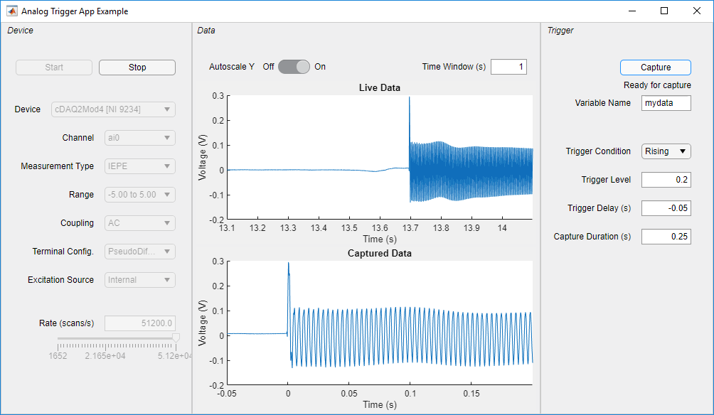
Device and Channel Configuration (left panel) — Select a connected DAQ device, choose an analog input channel, and configure measurement type, range, coupling, terminal configuration, and scan rate. Click Start to begin continuous acquisition or Stop to end it.
Live Data Display (center panel) — Displays a real-time scrolling plot of the acquired signal. Configure the visible time window and toggle Y-axis autoscaling.
Trigger and Capture (right panel) — Specify the trigger level, trigger condition (rising or falling), trigger delay, and capture duration. Click Capture to arm the trigger. If the trigger condition is met, the app captures data and saves it to a workspace variable.
Analog Trigger Condition
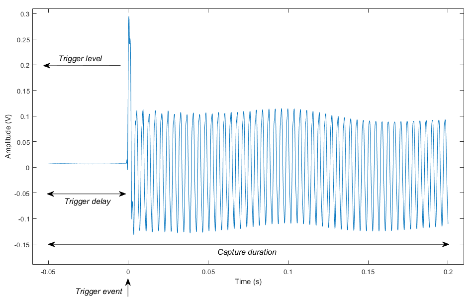
Four parameters define the analog trigger capture:
Trigger Level — The signal amplitude threshold.
Trigger Condition — Rising (signal crosses above the level) or Falling (signal crosses below the level).
Trigger Delay — Time offset from the trigger event to the start of the capture. A negative value captures pre-trigger data.
Capture Duration — Total length of the captured data segment.
App States for Controlling Operation
The app uses a state machine pattern to manage its operating modes. The CurrentState property tracks the active state, and the setAppViewState function enables or disables UI components based on the current state. The following list describes each state, when it becomes active, and the actions available in that state:
DeviceSelection— Active on app startup. You can select a DAQ device from the drop-down list.Configuration— Active after you select a device. You can configure channel properties and scan rate.Acquisition.Buffering— Active after you click Start. The app buffers pre-trigger data before arming the trigger.Acquisition.ReadyForCapture— Active after the app buffers enough data. You can click Capture to arm the trigger.Capture.LookingForTrigger— Active after you click Capture. The app monitors incoming data for the trigger condition.Capture.CapturingData— Active after the app detects the trigger. The app continues acquiring until the capture duration is met.Capture.CaptureComplete— Active after the capture completes. The app extracts the captured data and saves it to a workspace variable.
App Functions and Callbacks
This section describes the core functions and callbacks. Open the app in Code View in App Designer to view all callbacks, functions, and properties. Use the Code Browser pane to navigate the code.
scansAvailable_Callback Function
This callback executes periodically as the DataAcquisition object acquires data. It reads new data using the read function, stores it in a FIFO buffer, and updates the live scrolling plot. It also executes the state machine logic to transition between app states based on buffering status, trigger detection, and capture completion.
storeDataInFIFO Function
This function manages a finite-size circular buffer for continuous acquisition data. It appends new data and discards the oldest data to maintain a fixed buffer size. This enables smooth live plotting without continuously increasing memory use.
trigDetect Function
This function detects whether the trigger condition occurs in the latest acquired data. For a rising trigger, it finds the first data point where the signal crosses above the trigger level. For a falling trigger, it finds where the signal crosses below. The function returns a detection flag and the timestamp of the trigger moment.
completeCapture Function
This function extracts the capture data segment from the FIFO buffer based on the trigger moment and capture parameters. To align the capture to the trigger event, the function shifts timestamps so that time zero corresponds to the trigger moment. The function then saves the captured data as a timetable in the base workspace using assignin.
calculateBufferSize Function
This function determines the required FIFO buffer size based on the live view time window, trigger delay, capture duration, and scan rate. It retains enough data for both the live display and a complete triggered capture.
Callbacks for UI Components
The following list describes each UI component, its callback, and its behavior:
Device drop-down list (
DeviceDropDownValueChanged) — When you select a device, the callback populates channel and measurement options and creates a DAQ object usingdaqandaddinput.Start button (
StartButtonPushed) — When you click Start, the callback creates FIFO buffers, configures theScansAvailableFcncallback, and starts background acquisition usingstart.Stop button (
StopButtonPushed) — When you click Stop, the callback stops acquisition usingstopand resets to Configuration state.Capture button (
CaptureButtonValueChanged) — When you click Capture, the callback arms or cancels the trigger capture.Rate controls (
RateEditFieldValueChanged) — When you change the scan rate, the callback updates the DAQ scan rate and recalculates buffer sizes.Autoscale Y switch (
AutoscaleYSwitchValueChanged) — When you toggle the switch, the callback enables or disables Y-axis autoscaling on the live plot.

