poly2trellis
Convert convolutional code polynomials to trellis description
Syntax
Description
trellis = poly2trellis(ConstraintLength,CodeGenerator)ConstraintLength specifies the delay for the input bit
streams to the encoder. CodeGenerator specifies the output
connections for the input bit streams to the encoder.
The poly2trellis function accepts a polynomial description of a convolutional
encoder and returns the corresponding trellis structure description. This output can
be used as an input to the convenc and vitdec functions. It can also be used as a mask parameter value for
the Convolutional Encoder, Viterbi Decoder, and APP Decoder blocks.
Note
When used with a feedback polynomial, poly2trellis makes a feedback connection to the input of the trellis.
trellis = poly2trellis(ConstraintLength,CodeGenerator,FeedbackConnection)ConstraintLength specifies the delay for the input bit
streams to the encoder. CodeGenerator specifies the output
connections for the input bit streams to the encoder.
FeedbackConnection specifies the feedback connection for
each of the K input bit streams to the encoder.
Examples
Use a trellis structure to configure the rate 1/2 feedforward convolutional code in this diagram.
![Diagram of a rate 1/2 feedforward convolutional encoder with codegenerators [6 7] and constraint length 3](../../examples/comm/win64/TrellisStructFor12FeedforwardConvEncoderExample_01.png)
Create a trellis structure, setting the constraint length to 3 and specifying the code generator as a vector of octal values. The diagram indicates the binary values and polynomial form, indicating the left-most bit is the most-significant-bit (MSB). The binary vector [1 1 0] represents octal 6 and corresponds to the upper row of binary digits in the diagram. The binary vector [1 1 1] represents octal 7 and corresponds to the lower row of binary digits in the diagram. These binary digits indicate connections from the outputs of the registers to the two adders in the diagram.
trellis = poly2trellis(3,[6 7])
trellis = struct with fields:
     numInputSymbols: 2
    numOutputSymbols: 4
           numStates: 4
          nextStates: [4×2 double]
             outputs: [4×2 double]
Generate random binary data. Convolutionally encode the data, by using the specified trellis structure. Decode the coded data by using the Viterbi algorithm with the specified trellis structure, 34 for its traceback depth, truncated operation mode, and hard decisions.
data = randi([0 1],70,1);
codedData = convenc(data,trellis);
tbdepth = 34;
decodedData = vitdec(codedData,trellis,tbdepth,'trunc','hard');
Verify the decoded data has zero bit errors.
biterr(data,decodedData)
ans =
0
Create a trellis structure for a rate 2/3 feedforward convolutional code and display a portion of the next states of the trellis. See convenc for an example using this encoder.
The diagram shows a rate 2/3 encoder with two input streams, three output streams, and seven shift registers.
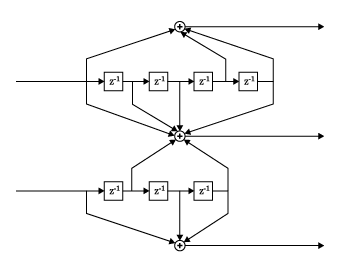
Create a trellis structure. Set the constraint length of the upper path to 5 and the constraint length of the lower path to 4. The octal representation of the code generator matrix corresponds to the taps from the upper and lower shift registers.
trellis = poly2trellis([5 4],[23 35 0; 0 5 13])
trellis = struct with fields:
     numInputSymbols: 4
    numOutputSymbols: 8
           numStates: 128
          nextStates: [128×4 double]
             outputs: [128×4 double]
The structure field numInputSymbols equals 4 because two bit streams can produce four different input symbols. The structure field numOutputSymbols equals 8 because three bit streams produce eight different output symbols. Because the encoder has seven total shift registers, the number of possible states is , as shown by the nextStates field.
Display the first five rows of the 128-by-4 trellis.nextStates matrix.
trellis.nextStates(1:5,:)
ans = 5×4

     0    64     8    72
     0    64     8    72
     1    65     9    73
     1    65     9    73
     2    66    10    74
Create a trellis structure to represent the rate 1/2 systematic convolutional encoder with feedback shown in this diagram.
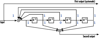
This encoder has 5 for its constraint length, [37 33] as its generator polynomial matrix, and 37 for its feedback connection polynomial.
The first generator polynomial is octal 37. The second generator polynomial is octal 33. The feedback polynomial is octal 37. The first generator polynomial matches the feedback connection polynomial because the first output corresponds to the systematic bits.
The binary vector [1 1 1 1 1] represents octal 37 and corresponds to the upper row of binary digits in the diagram. The binary vector [1 1 0 1 1] represents octal 33 and corresponds to the lower row of binary digits in the diagram. These binary digits indicate connections from the outputs of the registers to the two adders in the diagram. The initial 1 corresponds to the input bit.
Convert the polynomial to a trellis structure by using the poly2trellis function. When used with a feedback polynomial, poly2trellis makes a feedback connection to the input of the trellis.
trellis = poly2trellis(5,[37 33],37)
trellis = struct with fields:
     numInputSymbols: 2
    numOutputSymbols: 4
           numStates: 16
          nextStates: [16×2 double]
             outputs: [16×2 double]
Generate random binary data. Convolutionally encode the data by using the specified trellis structure. Decode the coded data by using the Viterbi algorithm with the specified trellis structure, 34 for its traceback depth, truncated operation mode, and hard decisions.
data = randi([0 1],70,1);
codedData = convenc(data,trellis);
tbdepth = 34; % Traceback depth for Viterbi decoder
decodedData = vitdec(codedData,trellis,tbdepth,'trunc','hard');
Verify the decoded data has zero bit errors.
biterr(data,decodedData)
ans =
0
Demonstrate alternative forms of specifying code generators for a trellis structure are equivalent.
![Diagram of a rate 1/2 feedforward convolutional encoder with codegenerators [12 15] and constraint length 3](../../examples/comm/win64/SpecifyingCodeGeneratorsInPolynomialFormExample_01.png)
Use a trellis structure to configure the rate 1/2 feedforward convolutional code in this diagram. The diagram indicates the binary values and polynomial form, indicating the left-most bit is the most-significant-bit (MSB).
Set the constraint length to 4. Use a cell array of polynomial character vectors to specify code generators. For more information, see Representation of Polynomials in Communications Toolbox. When using character representation to specify the code generator, you can specify the polynomial in ascending or descending order, but the poly2trellis function always assigns registers in descending order with the left-most register for the MSB.
trellis_poly = poly2trellis(4,{'x3 + x','x3 + x2 + 1'})trellis_poly = struct with fields:
numInputSymbols: 2
numOutputSymbols: 4
numStates: 8
nextStates: [8×2 double]
outputs: [8×2 double]
The binary vector [1 0 1 0] represents octal 12 and corresponds to the upper row of binary digits in the diagram. The binary vector [1 1 0 1] represents octal 15 and corresponds to the lower row of binary digits in the diagram. Use octal representation to specify the code generators for an equivalent trellis structure.
trellis = poly2trellis(4,[12 15])
trellis = struct with fields:
     numInputSymbols: 2
    numOutputSymbols: 4
           numStates: 8
          nextStates: [8×2 double]
             outputs: [8×2 double]
Use isequal to confirm the two trellises are equal.
isequal(trellis,trellis_poly)
ans = logical
   1
This example demonstrates creation of a nonstandard trellis structure for a convolutional encoder with uncoded bits and feedback. The encoder cannot be created using poly2trellis because the peculiar specifications for the encoder do not match the input requirements of poly2trellis.
You can manually create the trellis structure, and then use it as the input trellis structure for an encoder and decoder. The Convolutional Encoder and Viterbi Decoder blocks used in the Convolutional Encoder with Uncoded Bits and Feedback model load the trellis structure created here using a PreLoadFcn callback.
Convolutional Encoder
Create a rate 3/4 convolutional encoder with feedback connection whose MSB bit remains uncoded.
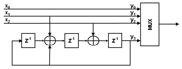
Declare variables according to the specifications.
K = 3;
N = 4;
constraintLength = 4;
Create trellis structure
A trellis structure has the following fields:
numInputSymbols– Number of input symbolsnumOutputSymbols– Number of output symbolsnumStates– Number of statesnextStates– Next state matrixoutputs– Output matrix
For more information about these structure fields, see istrellis.
Reset any previous occurrence of myTrellis structure.
clear myTrellis;Define the trellis structure fields.
myTrellis.numInputSymbols = 2^K;
myTrellis.numOutputSymbols = 2^N;
myTrellis.numStates  = 2^(constraintLength-1);
Create nextStates Matrix
The nextStates matrix is a [numStates x numInputSymbols] matrix. The (i,j) element of the next state matrix is the resulting final state index that corresponds to a transition from the initial state i for an input equal to j.
myTrellis.nextStates = [0  1  2  3  0  1  2  3; ...
                        6  7  4  5  6  7  4  5; ...
                        1  0  3  2  1  0  3  2; ...
                        7  6  5  4  7  6  5  4; ...
                        2  3  0  1  2  3  0  1; ...
                        4  5  6  7  4  5  6  7; ...
                        3  2  1  0  3  2  1  0; ...
                        5  4  7  6  5  4  7  6]
myTrellis = struct with fields:
     numInputSymbols: 8
    numOutputSymbols: 16
           numStates: 8
          nextStates: [8×8 double]
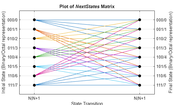
Plot nextStates Matrix
Use the commcnv_plotnextstates helper function to plot the nextStates matrix to illustrate the branch transitions between different states for a given input.
commcnv_plotnextstates(myTrellis.nextStates);
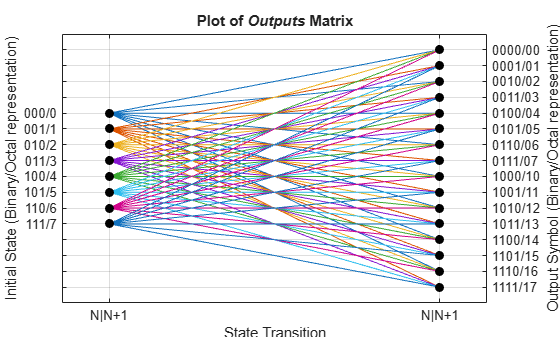
Create outputs Matrix
The outputs matrix is a [numStates x numInputSymbols] matrix. The (i,j) element of the output matrix is the output symbol in octal format given a current state i for an input equal to j.
outputs =  [0  2  4  6  10  12  14  16; ...
            1  3  5  7  11  13  15  17; ...
            0  2  4  6  10  12  14  16; ...
            1  3  5  7  11  13  15  17; ...
            0  2  4  6  10  12  14  16; ...
            1  3  5  7  11  13  15  17; ...
            0  2  4  6  10  12  14  16; ...
            1  3  5  7  11  13  15  17]
outputs = 8×8

     0     2     4     6    10    12    14    16
     1     3     5     7    11    13    15    17
     0     2     4     6    10    12    14    16
     1     3     5     7    11    13    15    17
     0     2     4     6    10    12    14    16
     1     3     5     7    11    13    15    17
     0     2     4     6    10    12    14    16
     1     3     5     7    11    13    15    17
Use oct2dec to display these values in decimal format.
outputs_dec = oct2dec(outputs)
outputs_dec = 8×8

     0     2     4     6     8    10    12    14
     1     3     5     7     9    11    13    15
     0     2     4     6     8    10    12    14
     1     3     5     7     9    11    13    15
     0     2     4     6     8    10    12    14
     1     3     5     7     9    11    13    15
     0     2     4     6     8    10    12    14
     1     3     5     7     9    11    13    15
Copy outputs matrix into the myTrellis structure.
myTrellis.outputs = outputs
myTrellis = struct with fields:
     numInputSymbols: 8
    numOutputSymbols: 16
           numStates: 8
          nextStates: [8×8 double]
             outputs: [8×8 double]
Plot outputs Matrix
Use the commcnv_plotoutputs helper function to plot the outputs matrix to illustrate the possible output symbols for a given state depending on the input symbol.
commcnv_plotoutputs(myTrellis.outputs, myTrellis.numOutputSymbols);
Check Resulting Trellis Structure
istrellis(myTrellis)
ans = logical
   1
A return value of 1 confirms the trellis structure is valid.
Decode with 3-bit soft decisions partitioned so that values near 0 map to 0, and values near 1 map to 7. If your application requires better decoding performance, refine the partition to obtain finer quantization.
The example decodes the code and computes the bit error rate. When comparing the decoded data with the original message, the example must take the decoding delay into account. The continuous operation mode of the Viterbi decoder causes a delay equal to the traceback length, so msg(1) corresponds to decoded(tblen+1) rather than to decoded(1).
System Setup
Initialize runtime variables for the message data, trellis, bit error rate computations, and traceback length.
stream = RandStream('mt19937ar', 'seed',94384);
prevStream = RandStream.setGlobalStream(stream);
msg = randi([0 1],4000,1); % Random data

trellis = poly2trellis(7,[171 133]); % Define trellis

ber = zeros(3,1); % Store BER values
tblen = 48; % Traceback length
Create an AWGN channel System object™, a Viterbi decoder System object, and an error rate calculator System object. Account for the receive delay caused by the traceback length of the Viterbi decoder.
awgnChan = comm.AWGNChannel('NoiseMethod','Signal to noise ratio (SNR)','SNR',6);
vitDec = comm.ViterbiDecoder(trellis,'InputFormat','Soft', ...
    'SoftInputWordLength',3,'TracebackDepth',tblen,'TerminationMethod','Continuous');
errorCalc = comm.ErrorRate('ReceiveDelay', tblen);
Run Coding and Decoding
Convolutionally code the message, pass in through an AWGN filter, quantize the noisy message for soft-decision decoding. Perform Viterbi decoding using the trellis generated using poly2trellis.
code = convenc(msg,trellis);
awgnChan.SignalPower = (code'*code)/length(code);
ncode = awgnChan(code);
Use quantiz to map the noisy data values to appropriate decision-value integers between 0 and 7. The second argument in quantiz is a partition vector that determines which data values map to 0, 1, 2, etc.
qcode = quantiz(ncode,[0.001,0.1,0.3,0.5,0.7,0.9,0.999]);
decoded = vitDec(qcode);
Compute bit error rate.
ber = errorCalc(msg,decoded);
ratio = ber(1)
ratio =
0.0013
number = ber(2)
number =
5
RandStream.setGlobalStream(prevStream);
Input Arguments
Output Arguments
Extended Capabilities
Version History
Introduced before R2006a