OFDM Demodulator Baseband
Demodulate using OFDM method
Libraries:
Communications Toolbox /
Modulation /
Digital Baseband Modulation /
OFDM
Description
The OFDM Demodulator Baseband block demodulates an input time domain signal by using the orthogonal frequency division multiplexing (OFDM) method. For more information, see OFDM Demodulation. The block accepts a single input and has one or two output ports, depending on the status of Pilot output port.
This icon shows the block with all ports enabled.
Examples
The model filters an oversampled OFDM modulated signal through a single-input single-output (SISO) channel. After channel filtering, it demodulates the signal and compares the original data to the demodulated output.
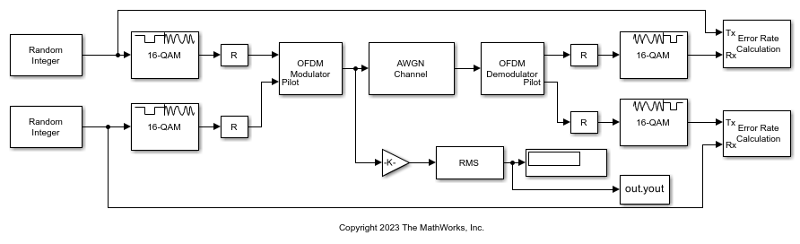
The cm_oversample_ofdm_siso
model:
Generates random integer data and pilot input symbols.
16-QAM modulates the data and pilot symbols.
OFDM-modulates the QAM-modulated signal. The OFDM modulator and demodulator pair process three symbols, with different pilot subcarrier indices and cyclic prefix lengths for each symbol. The OFDM signal contains data and pilots that the model generates at four times the sample rate.
Filters the OFDM-modulated signal through a SISO AWGN channel.
OFDM-demodulates and separately outputs the data and pilot signals.
16-QAM demodulates to the data and pilot symbols.
Computes symbol error rates for the data and pilot signals by using Error Rate Calculation blocks.
The model initializes variables used to configure block parameters by using the PreLoadFcn
callback function. For more information, see Model Callbacks (Simulink).
Display the data and pilot symbol error rates.
The data had a 0.014533 symbol error rate for 126126 samples. The pilots had a 0.014902 symbol error rate for 12012 samples.
The RMS block measures the OFDM-modulated signal scaled by a value proportional to the number of active subcarriers relative to the FFT size to confirm the signal power is approximately unity.
The measured RMS value is 0.98499.
Extended Examples
Digital Video Broadcasting - Terrestrial
Simulate part of the European Telecommunications Standards Institute (ETSI) EN 300 744 standard for terrestrial transmission of digital television signals.
Ports
Input
OFDM-modulated baseband signal, specified as an (osf × NIn)-by-NStreams matrix.
osf is the oversampling factor, as determined by Oversampling factor.
When
CyclicPrefixLength
is a scalar, NCP = Cyclic prefix length and NIn = NSym × (NFFT + NCP).When Cyclic prefix length is a row vector, NCPTotal =
sum
(Cyclic prefix length) and NIn = (NSym × NFFT) + NCPTotal.NSym is the number of symbols, as specified by Number of OFDM symbols.
NFFT is the number of subcarriers, as specified by FFT length.
NStreams is the number of receive streams specified by Number of receive antennas and must be less than or equal to the physical number of receive antennas.
Data Types: double
| single
Complex Number Support: Yes
Output
Output baseband signal, returned as a matrix or
NDataSC-by-NSym-by-NStreams
array of the same data type as the input signal. The output reduces to a
matrix when NStreams is
1
.
NDataSC is the number of data subcarriers, such that NDataSC = NFFT − NleftG − NrightG − NDCNull − NPilot − NCustNull.
NFFT is the number of subcarriers, as specified by FFT length.
NleftG is the number of subcarriers in the left guard band, as specified by the first element of Number of guard bands.
NrightG is the number of subcarriers in the right guard band, as specified by the second element of Number of guard bands.
NDCNull is the number of subcarriers in the DC null, specified as
0
or1
by selection of Remove DC carrier.NPilot is the number of pilot subcarriers in each symbol.
When you select Pilot output port, NPilot =
size
(Pilot subcarrier indices,1
).When you do not select Pilot output port, NPilot =
0
for the calculation of NOut.
NCustNull is the number of subcarriers used for custom nulls. To use custom nulls, you must specify Pilot subcarrier indices as a 3D array.
NSym is the number of symbols, as specified by Number of OFDM symbols.
NStreams is the number of receive streams, as specified by Number of receive antennas and is less than or equal to the physical number of receive antennas..
For more information, see Subcarrier Allocation, Guard Bands, and Guard Intervals.
Pilot signal, returned as an NPilot-by-NSym-by-NStreams array.
NPilot is the number of pilot subcarriers in each symbol, as determined by
size
(Pilot subcarrier indices,1
)NSym is the number of symbols, as specified by Number of OFDM symbols.
NStreams is the number of receive streams, as specified by Number of receive antennas and is less than or equal to the physical number of receive antennas..
Dependencies
To return this output, select Pilot output port.
Parameters
To edit block parameters interactively, use the Property Inspector. From the Simulink® Toolstrip, on the Simulation tab, in the Prepare gallery, select Property Inspector.
Number of FFT points, specified as a positive, integer scalar. The length of the FFT must be greater than or equal to 8 and is equivalent to the number of subcarriers.
Number of subcarriers allocated to the left and right guard bands, specified as a 2-by-1 integer vector. The number of left and right guard-band subcarriers, [NleftG; NrightG], must fall within [0,⌊NFFT/2⌋ − 1], where NFFT is the total number of subcarrier in the OFDM signal specified by FFT length. For more information, see Subcarrier Allocation, Guard Bands, and Guard Intervals.
Select this parameter to remove the null DC subcarrier. The null DC subcarrier is located at the center of the frequency band and has the index value:
(NFFT / 2) + 1 when NFFT is even.
(NFFT + 1) / 2 when NFFT is odd.
NFFT is the total number of subcarriers in the OFDM signal specified by FFT length.
Select this parameter to add a port to output pilot subcarriers. When you set this parameter to:
off
— Pilot information may be present but remains embedded in the output data.on
— The block separates the subcarriers, specified by Pilot subcarrier indices, from the output data and outputs the demodulated pilot signal to the Pilot port.
Indices of the pilot subcarrier locations, specified as a column vector, matrix, or 3D array with integer-element values in the range
where NFFT is the total number of subcarriers specified by FFT length, and NleftG and NrightG are the left and right guard bands specified by Number of guard bands.
You can assign the NPilot pilot carrier indices to the same or different NSym subcarriers for each symbol, and across NTxStreams transmit streams.
When the pilot indices are the same for every symbol and transmit antenna, the parameter has dimensions of NPilot-by-1.
When the pilot indices vary across symbols, the parameter has dimensions of NPilot-by-NSym.
If the received signal assigned one symbol across multiple transmit streams, the parameter has dimensions of NPilot-by-1-by-NTxStreams.
If the indices vary across the number of symbols and transmit streams, the parameter has dimensions of NPilot-by-NSym-by-NTxStreams.
Tip
To minimize interference between transmissions across more than one transmit stream, the pilot indices per symbol must be mutually distinct across the streams.
Dependencies
This parameter applies when you select Pilot output port.
Length of the cyclic prefix for each OFDM symbol, specified as a positive, integer scalar or row vector containing Number of OFDM symbols elements. The cyclic prefix length must be in the range [0, NFFT], where NFFT is the total number of subcarriers in the OFDM signal specified by FFT length. When you specify the cyclic prefix length as a:
Scalar — The cyclic prefix length is the same for all symbols through all streams.
Row vector — The cyclic prefix length may vary across symbols but does not vary across streams.
Oversampling factor, specified as a positive scalar. The oversampling factor must satisfy these constraints:
(Oversampling factor×FFT length) must be an integer value.
(Oversampling factor×Cyclic prefix length) must be an integer value.
Tip
If you set the oversampling factor to a noninteger rational number, specify a fractional value
rather than a decimal value. For example, with an FFT length of 12
and an
oversampling factor of 4/3
, their product is the integer
16
. However, rounding 4/3
to
1.333
when setting the oversampling factor results in a noninteger
product of 15.9960
, which results in a code error.
Number of OFDM symbols in the time-frequency grid, specified as a positive, integer scalar.
Number of receive streams to receive the OFDM modulated signal, specified
as a positive, integer scalar less than or equal to 64
.
The value must be less than or equal the physical number of receive
antennas.
Type of simulation to run, specified as Interpreted
execution
or Code generation
.
Interpreted execution
— Simulate the model by using the MATLAB® interpreter. This option requires less startup time, but the speed of subsequent simulations is slower than with theCode generation
option. In this mode, you can debug the source code of the block.Code generation
— Simulate the model by using generated C code. The first time you run a simulation, Simulink generates C code for the block. The model reuses the C code for subsequent simulations unless the model changes. This option requires additional startup time, but the speed of the subsequent simulations is faster than with theInterpreted execution
option.
For more information, see Interpreted Execution vs. Code Generation (Simulink).
Block Characteristics
Data Types |
|
Multidimensional Signals |
|
Variable-Size Signals |
|
Algorithms
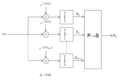
The orthogonal frequency division multiplexing (OFDM) method demodulates an OFDM input signal by using an FFT operation that results in N parallel data streams.
The figure shows an OFDM demodulator consisting of a bank of N correlators with one correlator assigned to each OFDM subcarrier. A parallel-to-serial conversion follows the correlator bank.
Individual OFDM subcarriers are allocated as data, pilot, or null subcarriers.
As shown here, subcarriers are designated as data, DC, pilot, or guard-band subcarriers.
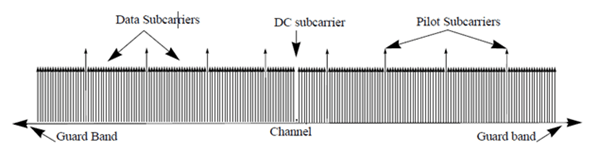
Data subcarriers transmit user data.
Pilot subcarriers are for channel estimation.
Null subcarriers transmit no data. Subcarriers with no data provide a DC null and serve as buffers between OFDM resource blocks.
The null DC subcarrier is the center of the frequency band with an index value of (
nfft
/2 + 1) ifnfft
is even, or ((nfft
+ 1) / 2) ifnfft
is odd.The guard bands provide buffers between adjacent signals in neighboring bands to reduce interference caused by spectral leakage.
Null subcarriers enable you to model guard bands and DC subcarrier locations for specific standards, such as the various 802.11 formats, LTE, WiMAX, or for custom allocations. You can allocate the location of nulls by assigning a vector of null subcarrier indices.
Similar to guard bands, guard intervals protect the integrity of transmitted signals in OFDM by reducing intersymbol interference.
Assignment of guard intervals is analogous to the assignment of guard bands. You can model guard intervals to provide temporal separation between OFDM symbols. The guard intervals help preserve intersymbol orthogonality after the signal passes through time-dispersive channels. You create guard intervals by using cyclic prefixes. Cyclic prefix insertion copies the last part of an OFDM symbol as the first part of the OFDM symbol.
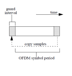
OFDM benefits from the use of cyclic prefix insertion as long as the span of the time dispersion does not exceed the duration of the cyclic prefix.
Inserting a cyclic prefix results in a fractional reduction of user data throughput because the cyclic prefix occupies bandwidth that could be used for data transmission.
References
[1] Dahlman, E., S. Parkvall, and J. Skold. 4G LTE/LTE-Advanced for Mobile Broadband. London: Elsevier Ltd., 2011.
[2] Andrews, J. G., A. Ghosh, and R. Muhamed. Fundamentals of WiMAX. Upper Saddle River, NJ: Prentice Hall, 2007.
[3] IEEE® Standard 802.16-2017. "Part 16: Air Interface for Broadband Wireless Access Systems." March 2018.
Extended Capabilities
C/C++ Code Generation
Generate C and C++ code using Simulink® Coder™.
Version History
Introduced in R2014aOFDM Demodulator Baseband
now supports oversampling.
See Also
Blocks
Objects
Functions
MATLAB Command
You clicked a link that corresponds to this MATLAB command:
Run the command by entering it in the MATLAB Command Window. Web browsers do not support MATLAB commands.
Select a Web Site
Choose a web site to get translated content where available and see local events and offers. Based on your location, we recommend that you select: .
You can also select a web site from the following list
How to Get Best Site Performance
Select the China site (in Chinese or English) for best site performance. Other MathWorks country sites are not optimized for visits from your location.
Americas
- América Latina (Español)
- Canada (English)
- United States (English)
Europe
- Belgium (English)
- Denmark (English)
- Deutschland (Deutsch)
- España (Español)
- Finland (English)
- France (Français)
- Ireland (English)
- Italia (Italiano)
- Luxembourg (English)
- Netherlands (English)
- Norway (English)
- Österreich (Deutsch)
- Portugal (English)
- Sweden (English)
- Switzerland
- United Kingdom (English)