M-APSK Demodulator Baseband
M-ary amplitude phase shift keying (APSK) demodulation
Libraries:
Communications Toolbox /
Modulation /
Digital Baseband Modulation /
APM
Description
The M-APSK Demodulator Baseband block demodulates a baseband representation of an M-ary amplitude phase shift keying (APSK) modulated signal. M is the Modulation Order for M-APSK. For a description of M-APSK demodulation, see APSK Hard Demodulation and APSK Soft Demodulation.
Note
M-APSK Demodulator Baseband specifically applies to multiple ring PSK constellations. For a single ring PSK constellation, use M-PSK Demodulator Baseband.
This icon shows the block with all ports enabled: ![]()
Examples
Apply 16-APSK modulation to a signal of random data. Pass the modulated signal through an AWGN channel. Demodulate the noisy 16-APSK signal. The example reports bit error rate (BER) and symbol error rate (SER) at two SNR settings.
The slex_16apsk_mod model passes a 16-APSK modulated signal through an AWGN channel, demodulates the signal and then computes the error rate statistics. The upper workflow computes the BER and the lower workflow computes the SER. Some block parameters get set by using workspace variables initialized in the PreLoadFcn callback function loads simulation variables into the workspace. For more information, see Model Callbacks (Simulink).
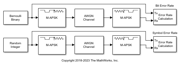
Run the model with the AWGN channel blocks set to EbN0 = 6 dB and display the computed BER and SER. The AWGN Channel block in the lower workflow converts the EbN0 setting to an EsN0 setting. The results are saved to the workspace variables BERVec and SERVec in 1-by-3 row vectors. The first element contains the error rate.
With EbN0 set to  6.00 dB, BER: 0.070
With EsN0 set to 12.02 dB, SER: 0.160
Change the EbN0 of the AWGN channel block to 10 dB. Run the model, display the computed BER and SER, and observe the decrease in error rate.
With EbN0 set to 10.00 dB, BER: 0.016
With EsN0 set to 16.02 dB, SER: 0.051
Ports
Input
Output
Parameters
Block Characteristics
Data Types |
|
Multidimensional Signals |
|
Variable-Size Signals |
|
More About
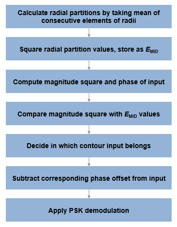
The hard demodulation algorithm applies amplitude phase decoding, as described in [1].
Tips
For faster execution of the M-APSK Demodulator Baseband block, set the Simulate using parameter to:
Code generationwhen using hard decision demodulation.Interpreted executionwhen using soft decision demodulation.
References
[1] Sebesta, J. “Efficient Method for APSK Demodulation.” Selected Topics on Applied Mathematics, Circuits, Systems, and Signals (P. Pardalos, N. Mastorakis, V. Mladenov, and Z. Bojkovic, eds.). Vouliagmeni, Athens, Greece: WSEAS Press, 2009.
[2] Liu, Z., Q. Xie, K. Peng, and Z. Yang. "APSK Constellation with Gray Mapping." IEEE Communications Letters. Vol. 15, Number 12, December 2011, pp. 1271–1273.
Extended Capabilities
Version History
Introduced in R2018b