General CRC Generator
Generate CRC code bits according to generator polynomial and append to input data frames
Libraries:
Communications Toolbox /
Error Detection and Correction /
CRC
Description
The General CRC Generator block generates cyclic redundancy check (CRC) code bits for each input data frame and appends them to the frame. For more information, see CRC Generator Operation.
Examples
Configure a CRC with the g(x) = x³ + x + 1 generator polynomial and indirect algorithm to append CRC bits to a frame by using Simulink® blocks and compare the results to the operation of the General CRC Generator block in the Communications Toolbox™ with the same configuration.
The cm_crcgen_indirect model runs both CRC generators with the register set to a specific initial state and for a known 6 bit long input message. The initial states are loaded into the workspace variable iniStates by using the PreLoadFcn callback function. For more information, see Model Callbacks (Simulink).
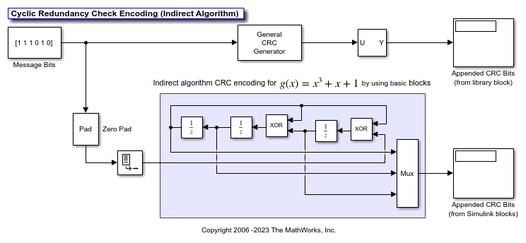
Running the simulation displays the appended CRC bits that are generated by using the General CRC Generator block and the CRC generated by using a generator polynomial built by using Simulink® blocks. View the model output to confirm that the results of both implementations match. You can run the model with different message bits or with different initial states. To adjust the initial states, change the iniStates workspace variable before to running the simulation.
For other changes to the CRC generator, such as specifying a higher order polynomial, you must revise the layout of the model blocks for the polynomial generator that is built from individual Simulink® blocks. However, to reconfigure the General CRC Generator block, you can simply update its parameter settings.
Configure a CRC with the g(x) = x³ + x + 1 generator polynomial and direct algorithm to append CRC bits to a frame by using Simulink® blocks and compare the results to the operation of the General CRC Generator block in the Communications Toolbox™ with the same configuration.
The cm_crcgen_direct model runs both CRC generators with the register set to a specific initial state and for a known 6 bit long input message. The initial states are loaded into the workspace variable iniStates by using the PreLoadFcn callback function. For more information, see Model Callbacks (Simulink).
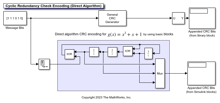
Running the simulation displays the appended CRC bits that are generated by using the General CRC Generator block and the CRC generated by using a generator polynomial built by using Simulink® blocks. View the model output to confirm that the results of both implementations match. You can run the model with different message bits or with different initial states. To adjust the initial states, change the iniStates workspace variable before to running the simulation.
For other changes to the CRC generator, such as specifying a higher order polynomial, you must revise the layout of the model blocks for the polynomial generator that is built from individual Simulink® blocks. However, to reconfigure the General CRC Generator block, you can simply update its parameter settings.
Generate a CRC-8 checksum for the example shown in 802.11™-2016, section 21.3.10.3 and compare with the expected CRC.
Explore the Model
To align with the CRC calculation in 802.11-2016, the General CRC Generator block mask sets the generator polynomial to  , initial states to 1, final XOR parameter to 1, and selects direct method.
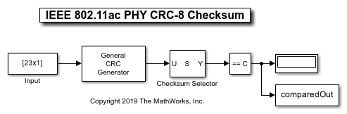
The simulation is configured to process one input frame modeling the example from the 802.11-2016 standard in section 21.3.10.3. In the example, the input bit stream {m0, … m22} is {1 0 0 1 1 0 0 0 0 0 0 0 0 0 0 0 0 0 0 0 0 1 1} and the expected CRC checksum {c7, … c0} is {0 0 0 1 1 1 0 0}. The generated CRC checksum bits are compared to the expected bits and a 1 is output for each equal bit in the 8 bit CRC checksum.
comparedOut =

  8×1 logical array

   1
   1
   1
   1
   1
   1
   1
   1
References
[1] IEEE Std 802.11™-2016 IEEE Standard for Information Technology—Local and Metropolitan Area Networks—Specific Requirements Part 11: Wireless LAN MAC and PHY Specifications.
Ports
Input
Output
Parameters
Block Characteristics
Data Types |
|
Multidimensional Signals |
|
Variable-Size Signals |
|
Algorithms
The General CRC Generator block supports generation of CRC checksum by using the indirect or direct CRC algorithm.
Indirect CRC Algorithm
The indirect CRC algorithm accepts a binary data vector, corresponding to a polynomial M, and appends a checksum of r bits, corresponding to a polynomial C. The concatenation of the input vector and the checksum then corresponds to the polynomial T = M×xr + C, since multiplying by xr corresponds to shifting the input vector r bits to the left. The algorithm chooses the checksum C so that T is divisible by a predefined polynomial P of degree r, called the generator polynomial.
The algorithm divides T by P, and sets the checksum equal to the binary vector corresponding to the remainder. That is, if T = Q×P + R, where R is a polynomial of degree less than r, the checksum is the binary vector corresponding to R. If necessary, the algorithm prepends zeros to the checksum so that it has length r.
The CRC generation feature, which implements the transmission phase of the CRC algorithm, does the following:
Left shifts the input data vector by r bits and divides the corresponding polynomial by P.
Sets the checksum equal to the binary vector of length r, corresponding to the remainder from step 1.
Appends the checksum to the input data vector. The result is the output vector.
The CRC detection feature computes the checksum for its entire input vector, as described above.
The CRC algorithm uses binary vectors to represent binary polynomials, in descending order of powers. For example, the vector [1 1 0 1] represents the polynomial x3 + x2 + 1.
Bits enter the linear feedback shift register (LFSR) from the lowest index bit to the highest index bit. The sequence of input message bits represents the coefficients of a message polynomial in order of decreasing powers. The message vector is augmented with r zeros to flush out the LFSR, where r is the degree of the generator polynomial. If the output from the leftmost register stage d(1) is a 1, then the bits in the shift register are XORed with the coefficients of the generator polynomial. When the augmented message sequence is completely sent through the LFSR, the register contains the checksum [d(1) d(2) . . . d(r)]. This is an implementation of binary long division, in which the message sequence is the divisor (numerator) and the polynomial is the dividend (denominator). The CRC checksum is the remainder of the division operation.
Direct CRC Algorithm
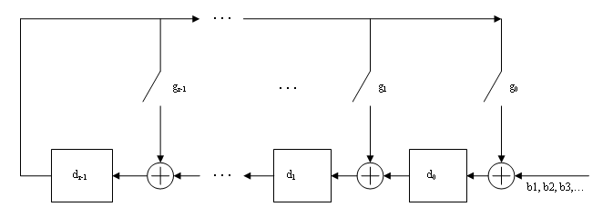
This block diagram shows the direct CRC algorithm.
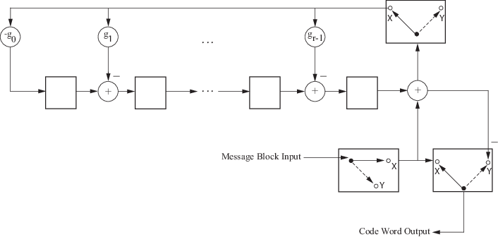
Where Message Block Input is and Code Word Output is
The initial step of the direct CRC encoding occurs with the three switches in position X. The algorithm feeds k message bits to the encoder. These bits are the first k bits of the code word output. Simultaneously, the algorithm sends k bits to the linear feedback shift register (LFSR). When the system completely feeds the kth message bit to the LFSR, the switches move to position Y. Here, the LFSR contains the mathematical remainder from the polynomial division. These bits are shifted out of the LFSR and they are the remaining bits (checksum) of the code word output.
The CRC generator appends CRC checksums to the input frame according to the specified generator polynomial and number of checksums per frame.
For a specific initial state of the internal shift register and k checksums per input frame:
The input signal is divided into k subframes of equal size.
Each of the k subframes are prefixed with the initial states vector.
The CRC algorithm is applied to each subframe.
The resulting checksums are appended to the end of each subframe.
The subframes are concatenated and output as a column vector.
For the scenario shown here, a 10-bit frame is input, a z3 + z2 + 1 generator polynomial computes the CRC checksum, the initial state is 0, and the number of checksums per frame is 2.
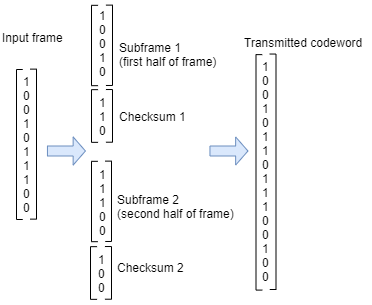
The input frame is divided into two subframes of size 5, and checksums of size 3 are computed
and appended to each subframe. The initial states are not shown because an initial state of
[0] does not affect the output of the CRC algorithm. The output
transmitted codeword frame has the size 5 + 3 + 5 + 3 = 16 bits.
References
[1] Sklar, Bernard. Digital Communications: Fundamentals and Applications. Englewood Cliffs, N.J.: Prentice-Hall, 1988.
[2] Wicker, Stephen B. Error Control Systems for Digital Communication and Storage. Upper Saddle River, N.J.: Prentice Hall, 1995.
Extended Capabilities
Version History
Introduced before R2006a