comm.SphereDecoder
Decode input using sphere decoder
Description
The comm.SphereDecoder
System object™ decodes the symbols sent over NT
antennas using the sphere decoding algorithm.
To decode symbols using the sphere decoding algorithm:
Create the
comm.SphereDecoderobject and set its properties.Call the object with arguments, as if it were a function.
To learn more about how System objects work, see What Are System Objects?
Creation
Syntax
Description
spheredecod = comm.SphereDecoderspheredecod. This object decodes the
symbols using the sphere decoding algorithm.
spheredecod = comm.SphereDecoder(const,bitTab)Constellation property to const and the
BitTable property to bitTab.
spheredecod = comm.SphereDecoder(___,Name=Value)spheredecod(InitialRadius="ZF solution") sets the initial search
radius of the decoding algorithm to "ZF solution".
Properties
Usage
Syntax
Description
Input Arguments
Output Arguments
Object Functions
To use an object function, specify the
System object as the first input argument. For
example, to release system resources of a System object named obj, use
this syntax:
release(obj)
Examples
Modulate a set of bits using a 16-QAM constellation, transmit the signal in two parallel streams over a MIMO channel, and decode the bits using a sphere decoder with perfect channel knowledge.
Specify the modulation order, the number of transmitted bits, and the symbol mapping.
bps = 4;                                               % Bits per symbol
M = 2^bps;                                             % Modulation order
nBits = 1e3*bps;                                       % Number of transmitted bits
symMap = [11 10 14 15 9 8 12 13 1 0 4 5 3 2 6 7];      % Symbol mapping
Generate and display the symbol mapping of the 16-QAM modulator by using the qammod function and the custom symbol map.
sym = qammod(symMap(1:M)',M,symMap, ...
    UnitAveragePower=true,PlotConstellation=true);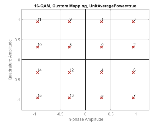
Convert the decimal values of the symbol map to binary bits, using the leftmost bit as the most significant bit (MSB). The sphere decoder utilizes the M-by-bps matrix, bitTable, for this purpose.
bitTable = int2bit(symMap,bps)';
Create a 2-by-2 MIMO Channel System object. To use the path gains as a channel estimate, set PathGainsOutputPort to true. To ensure the repeatability of results, set the object to use the global random number stream.
mimo = comm.MIMOChannel( ...
    PathGainsOutputPort=true, ...
    RandomStream="Global stream");
Create a Sphere Decoder System object to process bits using hard-decision decoding, and configure it with the custom bit table and symbol map.
sphDec = comm.SphereDecoder(Constellation=sym, ...
    BitTable=bitTable,DecisionType="Hard");
Create an error rate System object.
berRate = comm.ErrorRate;
Set the global random number generator seed.
rng(37)
Generate a random data stream.
data = randi([0 1],nBits,1);
Modulate the data and reshape it into two streams for the 2x2 MIMO channel.
modData = qammod(data,M,symMap, ...
    InputType="bit",UnitAveragePower=true);
modData = reshape(modData,[],2);
Pass the modulated data through the MIMO fading channel and add white Gaussian noise.
[fadedSig,pathGains] = mimo(modData);
rxSig = awgn(fadedSig,10);
Decode the received signal using pathGains as a perfect channel estimate.
decodedData = sphDec(rxSig,squeeze(pathGains));
Convert the decoded hard-decision data, which is a logical matrix, into a double-precision column vector to enable the calculation of error statistics. Then, calculate and display the bit error rate and the number of errors.
dataOut = double(decodedData(:));
errorStats = berRate(data,dataOut);
errorStats(1:2)
ans = 2×1

    0.1660
  664.0000
Limitations
The output LLR values are not scaled by the noise variance. For coded links employing iterative coding (LDPC or turbo) or MIMO OFDM with Viterbi decoding, scale the output LLR values by the channel state information to achieve better performance.
Algorithms
This object uses a soft-output Schnorr-Euchner sphere decoder (SESD), executed as a single tree search (STS) for tree traversal, to implement a soft-output max-log a posteriori probability (APP) detector for MIMO systems. The algorithm operates under the assumption that all transmit antennas use the same constellation and bit table. It takes the received symbol vector and the estimated channel matrix as inputs and outputs the log-likelihood ratios (LLRs) of the transmitted bits.
The algorithm models a MIMO system with NT transmit antennas and NR receive antennas. It assumes the system simultaneously transmits NT symbols, described by the equation y = Hs + n, where y is the received symbols, H is the MIMO channel matrix, s is the transmitted symbol vector, and n is the thermal noise.
The MIMO detector seeks the maximum-likelihood (ML) solution, , such that:
where O is the complex-valued constellation from which the detector selects the NT elements of s.
Soft detection also computes a log-likelihood ratio (LLR) for each bit that serves as a measure of the reliability of the estimate for each bit. The calculation of the LLR employs the max-log approximation:
where,
L(xj,b) is the LLR estimate for each bit.
is each sent bit, the bth bit of the jth symbol.
and are the disjoint sets of vector symbols that have the bth bit in the label of the jth scalar symbol equal to 0 and 1, respectively. The two λ symbols denote the distance calculated as norm squared, specifically:
is the distance .
is the distance to the counter-hypothesis, which denotes the binary complement of the bth bit in the binary label of the jth entry of , specifically the minimum of the symbol set , which contains all of the possible vectors for which the bth bit of the jth entry is flipped compared to the same entry of .
The equation for calculating the LLR estimate of bit varies depending on whether is 0 or 1:
The design of a decoder strives to efficiently find , , and .
The search can transform into a tree search through the sphere decoding algorithm. This involves decomposing the channel matrix into by means of a QR decomposition. Then, by left-multiplying y by QH, the problem reformulates as:
Using this reformulated problem statement, the triangular structure of R can be exploited to arrange a tree structure such that each of the leaf nodes corresponds to a possible s vector and the partial distances to the nodes in the tree can be calculated cumulatively adding to the partial distance of the parent node.
The STS algorithm searches the and metrics concurrently. The goal is to have a list containing the metric , along with the corresponding bit sequence and the metrics of all counter-hypotheses. The subtree originating from a given node is searched only if the result can lead to an update of either or .
The STS algorithm essentially involves these steps:
If when reaching a leaf node, a new ML hypothesis is found , all for which are set to which now turns into a valued counter-hypothesis. Then, is set to the current distance, d(x).
If , only the counter-hypotheses have to be checked. For all j and b for which and , the decoder updates to be d(x).
When a node's partial distance surpasses the current value—a value subject to change during subtree traversal—the algorithm decides to prune that sub-tree.
The STS algorithm stops when it has either visited each tree node once or pruned them.
References
[1] Studer, C., A. Burg, and H. Bolcskei. “Soft-Output Sphere Decoding: Algorithms and VLSI Implementation.” IEEE Journal on Selected Areas in Communications 26, no. 2 (February 2008): 290–300. https://doi.org/10.1109/JSAC.2008.080206.
[2] Cho, Yong Soo, ed. MIMO-OFDM Wireless Communications with MATLAB. Singapore ; Hoboken, NJ: IEEE Press : J. Wiley & Sons (Asia), 2010.
[3] Hochwald, B.M., and S. Ten Brink. “Achieving Near-Capacity on a Multiple-Antenna Channel.” IEEE Transactions on Communications 51, no. 3 (March 2003): 389–99. https://doi.org/10.1109/TCOMM.2003.809789.
[4] Agrell, E., T. Eriksson, A. Vardy, and K. Zeger. “Closest Point Search in Lattices.” IEEE Transactions on Information Theory 48, no. 8 (August 2002): 2201–14. https://doi.org/10.1109/TIT.2002.800499.
Extended Capabilities
Version History
Introduced in R2013a