Main Content

comm.gpu.PSKModulator

(To be removed) Modulate signals using M-PSK method with GPU

comm.gpu.PSKModulator will be removed in a future release. Use pskmod instead. (since R2026a) For information on updating your code, see Version History.

Description

The comm.gpu.PSKModulator object modulates a signal using the M-ary phase shift keying (M-PSK) method implemented on a graphics processing unit (GPU). The output is a baseband representation of the modulated signal.

To modulate a signal by using the M-PSK method:

  1. Create the comm.gpu.PSKModulator object and set its properties.

  2. Call the object with arguments, as if it were a function.

To learn more about how System objects work, see What Are System Objects?

Creation

Description

gpumpskmod = comm.gpu.PSKModulator creates a GPU-based modulator System object™, that modulates the input signal using the M-PSK method.

gpumpskmod = comm.gpu.PSKModulator(Name=Value) sets properties using one or more name-value arguments. For example, comm.gpu.PSKModulator(BitInput=true) specifies that input values must be binary.

gpumpskmod = comm.gpu.PSKModulator(M,Name=Value) sets the ModulationOrder property to M and sets optional name-value arguments.

example

gpumpskmod = comm.gpu.PSKModulator(M,phase,Name=Value) sets the ModulationOrder property to M, sets the PhaseOffset property to phase, and sets optional name-value arguments. Specify phase in radians.

Properties

expand all

Unless otherwise indicated, properties are nontunable, which means you cannot change their values after calling the object. Objects lock when you call them, and the release function unlocks them.

If a property is tunable, you can change its value at any time.

For more information on changing property values, see System Design in MATLAB Using System Objects.

Number of points in the signal constellation, specified as a positive integer.

Data Types: double

Phase of the zeroth point of the constellation in radians, specified as a scalar.

Example: PhaseOffset=0 aligns the QPSK signal constellation points on the axes {(1,0), (0,j), (-1,0), (0,-j)}.

Data Types: double

Option to provide input in bits, specified as a numeric or logical 0 (false) or 1 (true).

  • If you set this property to false, the input values must be integers in the range [0, (ModulationOrder – 1)].

  • If you set this property to true, the input values must be binary and the input vector length must be an integer multiple of the number of bits per symbol, log2(ModulationOrder).

Data Types: logical

Symbol encoding mapping of the constellation bits, specified as 'Gray', 'Binary', or 'Custom'. Each integer or group of log2(ModulationOrder) bits corresponds to one symbol.

  • When you set this property to 'Gray', the object maps symbols to a Gray-encoded signal constellation.

  • When you set this property to 'Binary', the object maps symbols to a natural binary-encoded signal constellation. Specifically, the complex value ej(PhaseOffset + (2πm/ModulationOrder)), where m is an integer in the range [0, (ModulationOrder1)].

  • When you set this property to 'Custom', the object maps symbols to the signal constellation defined in the CustomSymbolMapping property.

Custom symbol encoding, specified as an integer vector with length equal to the value of ModulationOrder and unique values in the range [0, (ModulationOrder1)]. The first element of this vector corresponds to the constellation point at an angle of 0 + PhaseOffset, with subsequent elements running counterclockwise. The last element corresponds to the constellation point at an angle of –2π/ModulationOrder + PhaseOffset.

Dependencies

To enable this property, set the SymbolMapping property to 'Custom'.

Data Types: double

Output data type, specified as either 'double' or 'single'.

Usage

Description

y = gpumpskmod(x) modulates the input signal by using the M-PSK method. The output is the modulated M-PSK baseband signal.

Input Arguments

expand all

Input signal, specified as a column vector of integers or bits. The BitInput property specifies the expected input values and vector length.

To decrease data transfer latency, format the input signal as a gpuArray (Parallel Computing Toolbox) object. For more information, see Array Processing with GPU-Based System Objects.

Data Types: double | single

Output Arguments

expand all

M-PSK modulated baseband signal, returned as a scalar or vector of complex-valued constellation symbols. The OutputDataType property specifies the data type of the output.

Object Functions

To use an object function, specify the System object as the first input argument. For example, to release system resources of a System object named obj, use this syntax:

release(obj)

expand all

constellationCalculate or plot ideal signal constellation
stepRun System object algorithm
releaseRelease resources and allow changes to System object property values and input characteristics
resetReset internal states of System object

Examples

collapse all

Create a GPU PSK modulator and demodulator pair.

gpuMod = comm.gpu.PSKModulator;
gpuDemod = comm.gpu.PSKDemodulator;

Generate random data symbols. Modulate the data.

txData = randi([0 7],1000,1);
txSig = gpuMod(txData);

Pass the signal through an AWGN channel.

rxSig = awgn(txSig,20);

Demodulate the received signal.

rxData = gpuDemod(rxSig);

Determine the number of symbol errors.

numSymErrors = symerr(txData,rxData)
numSymErrors =

     0

More About

expand all

Tips

To use this object, you must install Parallel Computing Toolbox™ and have access to a supported GPU. If the host computer has a GPU configured, processing uses the GPU. Otherwise, processing uses the CPU. For more information about GPUs, see GPU Computing (Parallel Computing Toolbox).

Algorithms

For higher-order PSK constellations, the complex baseband form for an M-ary PSK signal using binary-ordered symbol mapping is

sm(t)=exp(j(2πmM+ϕ));m{0,1,,M1}.

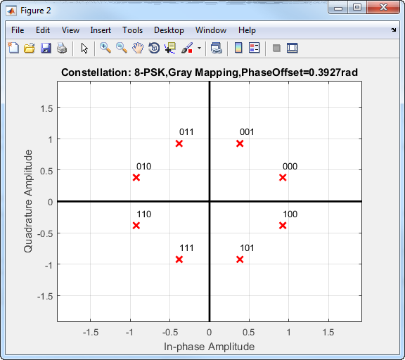
When the input is configured for bits, groups of log2(M) bits represent the complex symbols for the configured symbol mapping. The mapping can be binary encoded, Gray encoded, or custom encoded.

Gray coding has the advantage that only one bit changes between adjacent constellation points, which results in better bit error rate performance.

This 8-PSK constellation uses Gray-coded symbol mapping.

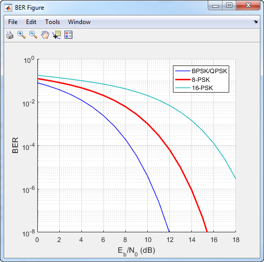
For modulation orders beyond 4, the bit error rate performance of PSK in AWGN worsens. In this bit error rate plot for Gray-coded mapping, the QPSK and BPSK curves overlap one another.

References

[1] Proakis, John G. Digital Communications. 4th ed. New York: McGraw Hill, 2001.

Extended Capabilities

expand all

Version History

Introduced in R2012a

collapse all

See Also

Functions

Objects

Blocks