Charge an Electric Vehicle
You can use the electric vehicle (EV) charging reference application to model charging of an EV battery, using either an NACS coupler (as introduced by Tesla®) or an SAE J1772/CCS coupler. The battery charging process includes digital communications between the electric vehicle and the electric vehicle supply equipment (EVSE) unit. The application provides four charging options, each utilizing a different combination of coupler and basic charging and high-level communication protocols, and incorporates a Datasheet Battery block without thermal management.
Use the EV charging reference application for control and diagnostic algorithm design and to test digital communication protocols. To create and open a working copy of the reference application project, use this command.
Charging Model Options
By default, the app opens an EvChargingNACS model. This model
simulates the NACS (North American Charging Standard), in the DC charging use case. To
execute another option, click the desired project under the Project
Shortcuts tab on the MATLAB® pane.
| Project Shortcut | Basic Charging Protocol | High-Level Communication Protocol | Coupler |
|---|---|---|---|
EvChargingNACS | IEC 61851 | DIN SPEC 70121 | NACS |
EvChargingAC | SAE J1772 | n/a | SAE J1772/CCS |
EvChargingCCS | IEC 61851 | ISO 15118 | SAE J1772/CCS |
EvChargingDC | SAE J1772 | DIN SPEC 70121 | SAE J1772/CCS |
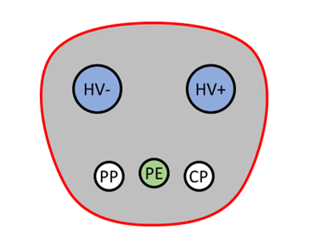
This table shows the NACS coupler (connector side) used in the first option, and describes the pins used for communication and charging.
| Pin Label | Name | Description | NACS Coupler |
|---|---|---|---|
HV+ | Power Terminal (+) | Positive power connection |
|
HV- | Power Terminal (-) | Negative power connection | |
PE | Ground (Protective Earth) | Common ground | |
CP | Control Pilot | Detects contact between connector and plug and carries the two way communication on a 1 kHz PWM signal | |
PP | Proximity Pilot | Detects proximity of connector to plug, even if not fully inserted, enabling warning of damage to connection hardware if vehicle or EVSE moves |
The other three options use the SAE J1772/CCS Combo Coupler, which is the combined charging system (CCS) version of the SAE J1772 coupler. This table shows the coupler (connector side) and describes the pins used for communication and charging.
| Pin Label | Name | Description | J1772/CCS Combo Coupler |
|---|---|---|---|
L1 | Line (AC1) | Single-phase AC power |
|
N | Neutral (AC2) | Neutral single-phase AC power | |
PE | Ground (Protective Earth) | Common ground | |
CP | Control Pilot | Detects contact between connector and plug and carries the two way communication on a 1 kHz PWM signal | |
CS | Proximity Detection/Proximity Contact/Connection Signal | Detects proximity of connector to plug, even if not fully inserted, enabling warning of damage to connection hardware if vehicle or EVSE moves | |
DC+ | DC Power Terminal (+) | Positive DC power connection | |
DC- | DC Power Terminal (-) | Negative DC power connection |

Simulate Model
To start charging, click Run. You can choose one of two views of the process. This first view shows the digital communications between the EV and the EVSE, shown in this image.
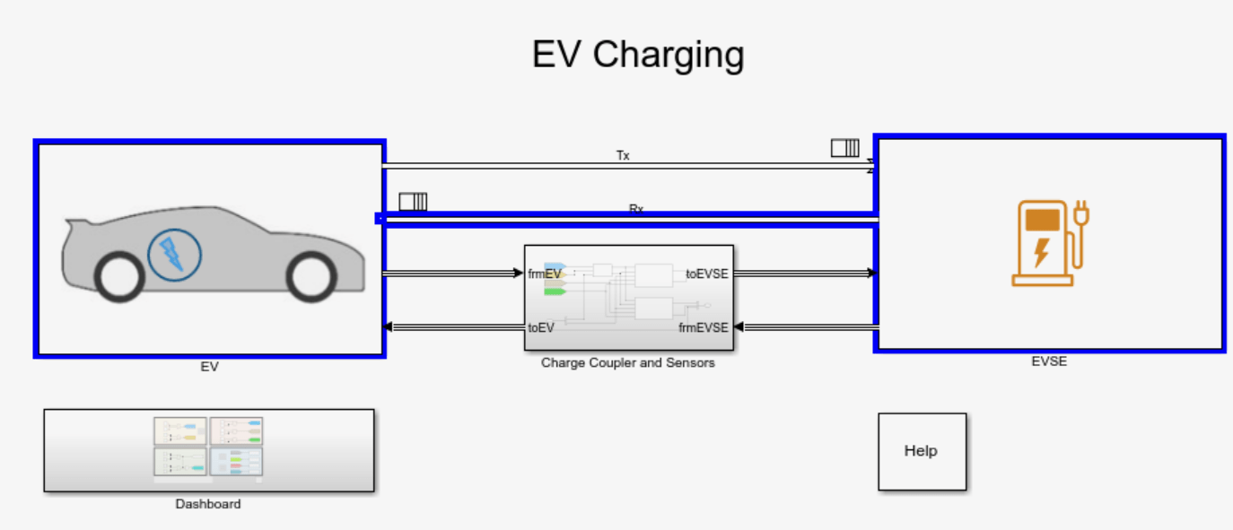
The app defaults to the dashboard view, shown in this image.

This view uses less animation than the first, so the app runs faster with the dashboard
displayed. The dashboard shows the states of the charging coupler, the readiness of the
EV and EVSE to charge, and the authentication and authorization to charge. Numerical
displays show the rate and progress of the charge. Alternatively, you can turn off the
animation for the top level model. On the Debug tab set
Animation speed to None in the
Event Animation section.
This table summarizes the switch options, indicator lights, and charging statuses shown in the dashboard.
| Dashboard Section | Switch, Indicator Light, or Status | Description |
|---|---|---|
Power Connector, Control Pilot & Proximity Detection |
| Switch output indicating if the vehicle is plugged in
( |
| Switch output indicating if the mechanical latch lever
position is released ( | |
| Indicator light switches from red to green when the connector is locked. | |
System status for EV & EVSE |
| Switch output indicating if a supercharger
( |
| Switch output indicating if the charger is ready to supply
energy ( | |
| Switch output indicating if the power to the charger is on
( | |
Authentication |
| Switch output indicating the user has requested charging to
start ( |
| Switch output indicating payment has been authenticated
( | |
Charging Status | ChargingState | Status indicating the charging state. See Charging States. |
BattSOC | Status indicating the battery state of charge percent. | |
BattCurr | Status indicating the current output during charging. | |
DutyCycle | Status indicating the duty cycle during charging. | |
Charge Status Indicator | Indicator light switches from red to green when the vehicle is connected and ready to charge and if the EVSE is ready to supply energy. | |
AC Present Indicator | Indicator light switches from red to green when the charger is powered. |
Charging States
As you develop your model, you can replace the manual switches with timed or triggered ones and verify their actions.
Here is a table of Charging_State values and their descriptions,
for the IEC 61851 basic charging protocol.
System states detected by EV supply equipment (EVSE) per IEC 61851-1:2017
| State Designation | EV Status | EVSE Status |
|---|---|---|
| A1 | Vehicle not connected | EVSE not ready |
| A2 | Vehicle not connected | EVSE ready |
| B1 | Vehicle connected & not ready to accept energy | EVSE not ready to supply energy |
| B2 | Vehicle connected & not ready to accept energy | EVSE ready to supply energy |
| C1 | Vehicle connected & ready to accept energy/EV does not require charging area ventilation | EVSE not ready to supply energy |
| C2 | Vehicle connected & ready to accept energy/EV does not require charging area ventilation | EVSE ready to supply energy |
| D1 | Vehicle connected & ready to accept energy/EV requires charging area ventilation | EVSE not ready to supply energy |
| D2 | Vehicle connected & ready to accept energy/EV requires charging area ventilation | EVSE ready to supply energy |
| E | EVSE disconnected from vehicle / EVSE disconnected from utility, EVSE loss of utility power or control pilot short to control pilot reference | |
| F | Other EVSE problem | |
Here is a table of Charging_State values and their descriptions,
for the SAE J1772 basic charging protocol.
System states detected by EV supply equipment (EVSE) per SAE J1772:2017
| State Designation | Description |
|---|---|
| A | Vehicle not connected |
| B1 | Vehicle connected / not ready to accept energy EVSE not ready to supply energy |
| B2 | Vehicle connected / not ready to accept energy EVSE capable to supply energy |
| C | Vehicle connected / ready to accept energy / indoor area charging ventilation not required EVSE capable to supply energy |
| D | Vehicle connected / ready to accept energy / indoor area charging ventilation required EVSE capable to supply energy |
| E | EVSE disconnected from vehicle / EVSE disconnected from utility, EVSE loss of utility power or control pilot short to control pilot reference |
| F | Other EVSE problem |
Notes:
States D, D1 and D2 for basic charging are not implemented in the reference application.
High level communication (HLC) evaluates application layer messages, logic, and timing management for electric vehicle charging communication protocols. Physical layers and other OSI layers mentioned in the protocols are not implemented in the reference application.
Charging Analysis
Once charging is complete, you can display the results in the Simulation Data Inspector versus time. You can select results for battery current, battery state of charge, charging status, and others. See View Simulation Data in Simulation Data Inspector.

You can also use the Sequence Viewer to see the communications between the EV and the EVSE. See Use the Sequence Viewer to Visualize Messages, Events, and Entities (Stateflow).

See Also
Datasheet Battery | Mapped Motor
Topics
- EV Charging Reference Application
- Simulation Data Inspector
- Use the Sequence Viewer to Visualize Messages, Events, and Entities (Stateflow)