SNR Definition Used in Link Simulations
This example shows how 5G Toolbox™ link-level simulations define the signal-to-noise ratio (SNR) for time-domain and frequency-domain channel modeling.
SNR Definition
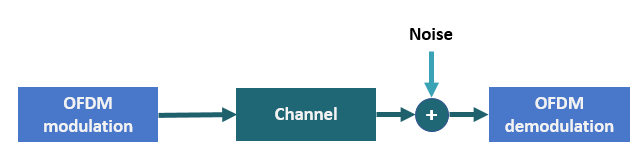
5G Toolbox™ examples that simulate link-level simulations define the SNR as the average SNR per resource element (RE) per receive antenna. They define the REs in the resource grid, that is, in the frequency domain. To achieve the desired SNR, the examples scale the noise. Some examples use time-domain channel models, while others use frequency-domain channel models. These examples scale the noise differently depending on the channel modeling.
The SNR definition used by the examples is
.
and are the average signal power per RE per receive antenna and the average noise power per RE per receive antenna, respectively. models the AWGN that the examples add to the signal.
In 5G, the signal of interest does not use all FFT bins (or REs) due to the presence of guard bands or zero padding. Additionally, the signal allocation can occupy only a part of the available grid. If the signal uses only bins of the FFT, the signal power per RE is
.
is the signal power over an OFDM symbol, and is the number of nonzero power REs per OFDM symbol.
However, the noise spans all FFT bins. Therefore, the noise power per RE is
.
is the noise power, and is the size of the OFDM FFT. Considering these definitions, the SNR becomes
.
Noise Scaling for Time-Domain Channel Modeling
The NR PDSCH Throughput and NR PUSCH Throughput examples introduce AWGN to the received signal in the time domain, after the fading channel and before OFDM demodulation.
For a signal with discrete Fourier transform (DFT) , Parseval's theorem states
.
Divide the equation by to get the average signal power
.
Because the signal of interest uses only bins (or REs) of the FFT, the signal power per RE is
.
Then the SNR becomes
.
The symbol modulator in 5G Toolbox returns symbols satisfying the condition . A CDL or TDL channel model with the NormalizeChannelOutputs property set to true normalizes the channel outputs by the number of receive antennas . Therefore, the examples assume that .
.
The noise power at the input of the OFDM demodulator is
.
To generate noise with power , the examples scale the complex random samples by .
.
Most 5G Toolbox examples that model a link use this scaling factor. This scaling factor assumes that the root mean squared of the signal RE values is . This assumption does not always apply when using a propagation channel.
The propagation channel introduces a number of effects, such as correlation, antenna polarization, and antenna element gain. These channel effects can impact the signal power at the receiver. These effects make estimating the SNR at the receiver and setting up a simulation to model a specific SNR difficult. To overcome this difficulty, the SNR definition in the examples does not consider any of the channel effects. The SNR definition matches the SNR that they measure without a fading channel and when .
When you use a propagation channel (nrTDLChannel or nrCDLChannel object), consider that:
When the
NormalizeChannelOutputsproperty of the channel objects is set totrue, the channel outputs are normalized by the number of receive antennas, and , as assumed in the derivation.To ensure that the channel paths do not alter the power of the transmitted signal and that the condition remains valid at the reciever end for each path, set the
NormalizePathGainsproperty of the channel objects totrue. The total power of the average path gains is then set to0.The SNR definition does not consider channel effects such as antenna orientation, antenna element gain, array gain, multipath interference, polarization, and antenna correlation.
SNR Verification for Time-Domain Channel Modeling
From the equation derived in Noise Scaling for Time-Domain Channel Modeling, you can verify the SNR. Because the introduced SNR definition does not account for any of the channel effects, this verification does not include a propagation channel.
This figure shows the setup to measure the SNR per RE per antenna.
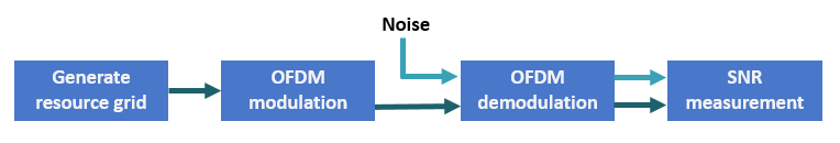
For this setup, implement these steps:
Generate a resource grid with physical downlink shared channel (PDSCH) symbols.
OFDM-modulate the grid.
Generate AWGN.
OFDM-demodulate the received signal and the noise separately.
Measure the power of the signal and the noise per RE per antenna.
Calculate and display the SNR.
Specify the desired SNR in dB.
SNRdB = 0;
rng("default") % Enable reproducible simulation results
Set the number of transmit and receive antennas. Because no channel exists, assume that the number of transmit and receive antennas is the same.
nTxAnts = 2;
nRxAnts = nTxAnts;
Specify the carrier parameters.
carrier = nrCarrierConfig;
carrier.NSizeGrid = 52;                     % Grid size in resource blocks
carrier.SubcarrierSpacing = 15;             % Subcarrier spacing

waveformInfo = nrOFDMInfo(carrier);         % Waveform information

pdsch = nrPDSCHConfig;
pdsch.Modulation = "16QAM";
pdsch.PRBSet = 0:(carrier.NSizeGrid-1);     % PDSCH allocation
Create a norm-one precoding vector that is normalized by the number of layers.
w = (1/sqrt(pdsch.NumLayers))*ones(pdsch.NumLayers,nTxAnts);
To achieve the desired SNR, calculate the noise scaling factor: .
SNR = 10^(SNRdB/10);
N0time = 1/sqrt(nRxAnts*double(waveformInfo.Nfft)*SNR);
Generate precoded PDSCH symbols.
[pdschIndices,pdschInfo] = nrPDSCHIndices(carrier,pdsch);
pdschBits = randi([0 1],pdschInfo.G,1);
pdschSymbols = nrPDSCH(carrier,pdsch,pdschBits);
pdschSymbolsPrecoded = pdschSymbols*w;
Create a resource grid and map the precoded PDSCH symbols to the resource grid.
pdschGrid = nrResourceGrid(carrier,nTxAnts);
[~,pdschAntIndices] = nrExtractResources(pdschIndices,pdschGrid);
pdschGrid(pdschAntIndices) = pdschSymbolsPrecoded;
OFDM-modulate the grid.
txWaveform = nrOFDMModulate(carrier,pdschGrid);
Assume no channel exists. Because the SNR definition assumes that , normalize the received signal by the number of receive antennas.
rxWaveform = txWaveform/sqrt(nRxAnts);
Generate AWGN.
rxNoise = N0time*randn(size(rxWaveform),"like",rxWaveform);OFDM-demodulate the received signal (without noise), and extract the PDSCH symbols from the received grid to calculate .
% OFDM demodulation
rxSignalGrid = nrOFDMDemodulate(carrier,rxWaveform);

% PDSCH symbols extraction
rxPDSCHSymbols = rxSignalGrid(pdschAntIndices);
Measure the received signal power per RE, , and the noise power per RE, .
Verify that the measured SNR values approximate the specified SNR parameter.
Sre = (1/waveformInfo.Nfft.^2)*rms(rxPDSCHSymbols).^2;
Nre = (1/waveformInfo.Nfft)*rms(rxNoise).^2;
for n=1:nRxAnts
    disp("Received signal power per RE antenna " + string(n) + " = " + string(pow2db(Sre(n))+30) + " dBm");
    disp("Received noise power per RE antenna " + string(n) + " = " + string(pow2db(Nre(n))+30) + " dBm");
    disp("SNR (antenna " + string(n) + ") = " + string(pow2db(Sre(n)/Nre(n))) + " dB");
end
Received signal power per RE antenna 1 = -33.186 dBm
Received noise power per RE antenna 1 = -33.2182 dBm
SNR (antenna 1) = 0.032227 dB
Received signal power per RE antenna 2 = -33.186 dBm
Received noise power per RE antenna 2 = -33.2622 dBm
SNR (antenna 2) = 0.076224 dB
Noise Scaling for Frequency-Domain Channel Modeling
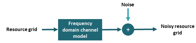
The 5G Toolbox link-level examples with a frequency domain channel model apply the noise in the frequency-domain, that is, to the resource grid.
The SNR definition derived so far includes the average noise power N.
Using Parseval's theorem, the average noise power is
.
is the DFT of the noise signal . Considering this definition
.
The power of the noise samples in the frequency domain is
.
Therefore, in order to generate noise samples of the appropriate power in the frequency domain, the scaling factor will be as follows:
.
SNR Verification for Frequency-Domain Channel Modeling
From the equation derived in Noise Scaling for Frequency-Domain Modeling, you can verify the SNR. Because the introduced SNR definition does not account for any of the channel effects, this verification does not include a propagation channel.
This figure shows the setup to measure the noise power in the frequency domain.
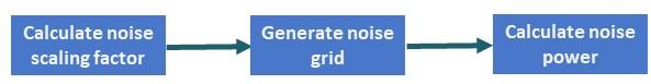
For this setup, implement these steps:
Use the equation from Noise Scaling for Frequency-Domain Channel Modeling to generate noise in the frequency domain.
Apply the noise in the frequency domain and measure the noise power.
Obtain noise power in time-domain and compare with the frequency domain.
Specify the desired SNR in dB.
SNRdB = 0;
rng("default") % Enable reproducible simulation results
Set the number of transmit and receive antennas. Because no channel exists, assume that the number of transmit and receive antennas is the same.
nTxAnts = 2;
nRxAnts = nTxAnts;
Configure the carrier and extract the OFDM information.
carrier = nrCarrierConfig;
ofdmInfo = nrOFDMInfo(carrier);
Convert the SNR to power.
SNR = 10.^SNRdB/10;
Using the equation derived above, generate noise in the frequency domain and measure its power.
N0freq = 1/sqrt(nRxAnts*SNR);
noiseGridFreq = zeros(size(pdschGrid),'like',1i);

noiseGridFreq(:) = N0freq*randn(size(noiseGridFreq),'like',1i);     % Resource grid for noise generated in the frequency domain

noisePowerFreq = rms(noiseGridFreq(:)).^2;                          % Power of noise added in the frequency domain
Generate noise in the time-domain, and measure the power after OFDM modulation.
grid = nrResourceGrid(carrier);
waveform = nrOFDMModulate(carrier,grid);                            % This is only necessary when for obtaining the correct signal sizes (with CPs, etc...)

N0time = 1/sqrt(nRxAnts*ofdmInfo.Nfft*SNR);
noise = N0time*randn([size(waveform,1) nRxAnts],'like',1i);

noiseGridTime = nrOFDMDemodulate(carrier,noise);                    % Resource grid for noise generated in the time domain

noisePowerTime = rms(noiseGridTime(:)).^2;                          % Power of noise added in the time domain
The generated noise power in the frequency domain is similar to the generated noise power in the time domain. These values represent the noise power that is needed to achieve the specified SNR.
for x = 1
    disp("Frequency-domain channel modeling noise power: "+noisePowerFreq)
    disp("Time-domain channel modeling noise power: "+noisePowerTime)
end
Frequency-domain channel modeling noise power: 4.9115
Time-domain channel modeling noise power: 4.9932