energyDetector
Add-On Required: This feature requires the Wireless Testbench™ Support Package for NI™ USRP™ Radios add-on.
Description
Use the energyDetector object to configure the
specified software-defined radio (SDR) as an energy detector. You can use
the energy detector to detect and capture a signal of interest from the
air using an increase in signal energy as the trigger. The object
specifies the energy threshold and triggering parameters. For details, see
Internal Architecture of Energy Detection.
This diagram shows a conceptual overview of detecting and capturing radio signals in Wireless Testbench™ using a radio that you configure with this object. The object also enables you to send a test waveform for detection and capture. The onboard data buffering ensures contiguous data capture and transmit.
Creation
Description
ed = energyDetector(radio)radio.
Note
The object requires exclusive access to radio hardware resources. Before creating this object, clear any existing Wireless Testbench application object associated with the specified radio from the workspace.
ed = energyDetector(radio,PropertyName=Value)CaptureDataType="double" sets the data type of the returned captured
signal to double.
Input Arguments
Radio setup configuration, specified as one of these options.
String scalar — The name of a radio setup configuration you saved using the Radio Setup wizard. To list all saved radio setup configurations, call the
radioConfigurationsfunction with no input arguments. For example,"MyRadio".Radio object — A radio object that corresponds to a radio setup configuration you saved using the Radio Setup wizard. For example, to create a radio object for a radio setup configuration with the name
"MyRadio", callradio = radioConfigurations("MyRadio").Use this option when you want to use synchronization features. You can refer to radio object properties to get information about the radio setup configuration that the object corresponds to, such as the model number of the radio, the radio IP address, and the synchronization options. Additionally, you can:
Check the lock status of the reference clock, local oscillators, or GPS disciplined oscillator (GPSDO) on the radio using the
referenceLockedStatus,loLockedStatus, andgpsLockedStatusfunctions respectively.Get the current radio time using the
getRadioTimefunction.Synchronize multiple devices by setting the radio time using the
getTimeLastPPSandsetTimeNextPPSfunctions.Get time and GPS information from the radio using the
getGPSTimeandgetGPSNMEAfunctions.Schedule synchronized property updates on your
energyDetectorobject using thesetCommandTime,getCommandTime, andclearCommandTimefunctions.
For more information, see Time Synchronize Operations on NI USRP Radios.
For a list of supported radios, see Supported Radio Devices.
Properties
Capture center frequency in Hz, specified as a positive numeric scalar. The valid center frequency range depends on the radio device.
| Radio Device | Center Frequency |
|---|---|
USRP™ N300 | 1 MHz to 6 GHz |
USRP N310 | 1 MHz to 6 GHz |
USRP N320 | 1 MHz to 6 GHz |
USRP N321 | 1 MHz to 6 GHz |
USRP X300 | 10 MHz to 6 GHz |
USRP X310 | 10 MHz to 6 GHz |
USRP X410 | 1 MHz to 8 GHz |
Data Types: double
Capture radio gain in dB, specified as a positive numeric scalar. The valid gain range depends on the radio device.
| Radio Device | Capture Radio Gain |
|---|---|
USRP N300 | 0 dB to 75 dB |
USRP N310 | 0 dB to 75 dB |
USRP N320 | 0 dB to 60 dB |
USRP N321 | 0 dB to 60 dB |
USRP X300 | 0 dB to 31.5 dB |
USRP X310 | 0 dB to 31.5 dB |
USRP X410 | 0 dB to 60 dB |
Data Types: double
Capture radio antenna, specified as a string scalar. Use this table to identify a supported radio antenna port on the radio device and the corresponding string constant that you can specify for this property. The default value depends on the radio.
| Radio Device | Supported Antenna Port | String Scalar |
|---|---|---|
USRP N300 | RF0 channel: RX2 port | "RF0:RX2" (default) |
| RF1 channel: RX2 port | "RF1:RX2" | |
USRP N310 | RF0 channel: RX2 port | "RF0:RX2" (default) |
| RF1 channel: RX2 port | "RF1:RX2" | |
| RF2 channel: RX2 port | "RF2:RX2"
| |
| RF3 channel: RX2 port | "RF3:RX2" | |
USRP N320 | RF0 channel: RX2 port | "RF0:RX2" (default) |
| RF1 channel: RX2 port | "RF1:RX2" | |
USRP N321 | RF0 channel: RX2 port | RF0 channel: RX2 port |
| RF0 channel: RX2 port | RF0 channel: RX2 port | |
USRP X300 | RFA channel: RX2 port |
|
RFB channel: RX2 port |
| |
USRP X310 | RFA channel: RX2 port |
|
RFB channel: RX2 port |
| |
| USRP X410 | DB0 RF0 channel: RX 1 port |
|
DB0 RF1 channel: RX 1 port |
| |
DB1 RF0 channel: RX 1 port |
| |
DB1 RF1 channel: RX 1 port |
|
Note
When you update this property, the execution time of the next object function call increases by a few seconds.
Data Types: string
Baseband sample rate in Hz, specified as a positive numeric scalar. For more information on how the radio achieves the specified sample rate, see Baseband Sample Rate in NI USRP Radios.
The sample rate depends on the radio device.
| Radio Device | Sample Rate |
|---|---|
USRP N300 |
|
USRP N310 | |
USRP N320 |
|
USRP N321 | |
USRP X300 |
|
USRP X310 | |
USRP X410 |
|
Note
To update this property, you must stop any ongoing transmission by calling the stopTransmission
function on the object. When you update this property, the execution time of the next object
function call increases by a few seconds.
Data Types: double
Data type of the captured data, specified as "int16",
"double", or "single". Use this property to
set the data type of the captured data that the capture
object function returns.
Note
When you update this property, the execution time of the next object function call increases by a few seconds.
Data Types: string
Since R2024a
Unit of capture request timestamp, specified as
"datetime" or
"sample-clock-cycle". Use this property to set
the data type of the timestamp that the capture object function returns.
Data Types: string
Behavior of the capture or plotDetectionSignals object functions upon dropped
samples, specified as one of these values.
"error"— The object function stops with an error message."warning"— The object function displays a warning message."none"— The object function ignores dropped samples.
Data Types: string
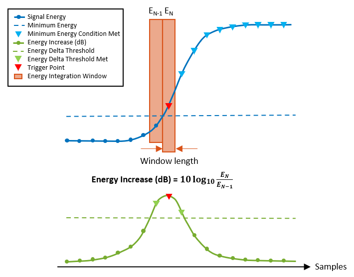
Energy integration window length, specified as a numeric scalar in the range [0, 4095]. The number of samples in the sliding window that is used to calculate the signal energy and the energy increase. For details, see Thresholding and Triggering.
Data Types: double
Threshold calculation method to trigger data capture, specified as one of these values.
"adaptive"— Two thresholds must be met to trigger a data capture. The energy increase in dB, which is the ratio between the signal energy in the current window and the signal energy in the previous window, is compared against a constant threshold specified by theEnergyDeltaThresholdproperty. The signal energy is also compared against a constant threshold, specified by theMinimumEnergyproperty. Together, these thresholds are adaptive to channel noise."fixed"— The signal energy is compared against a constant threshold, specified by theFixedThresholdproperty.
For details, see Algorithms.
Note
To update this property, you must stop any ongoing transmission by calling the stopTransmission
function on the object. When you update this property, the execution time of the next object
function call increases by a few seconds.
Data Types: string
Fixed threshold value, specified as a numeric scalar in the range [0, 8191]. For details, see Thresholding and Triggering.
Dependencies
This property applies only when you set ThresholdMethod to
"fixed".
Data Types: double
Minimum energy threshold value, specified as a numeric scalar in
the range [0, 8191]. This value is the minimum energy at which the
EnergyDeltaThreshold is applied in adaptive threshold
mode. Set this threshold relative to the noise floor so that noise
variations under this level do not cause false triggers. For
details, see Thresholding and Triggering.
Dependencies
This property applies only when you set ThresholdMethod to
"adaptive".
Data Types: double
Energy delta threshold, specified as the energy increase
threshold in dB. This value is the ratio between the signal energy
in the current window and the signal energy in the previous window,
expressed in decibels. Set this threshold relative to the WindowLength property. For example:
An energy increase of 3 dB corresponds to a two-fold increase in signal energy between two adjacent windows.
An energy increase of 20 dB corresponds to a one-hundred-fold increase in signal energy between two adjacent windows.
For details, see Thresholding and Triggering.
Dependencies
This property applies only when you set ThresholdMethod to
"adaptive".
Data Types: double
Trigger point offset, specified as an integer in the range [–4095, 4096]. This value specifies the start of data capture relative to the trigger point. For details, see Thresholding and Triggering.
Note
To update this property, you must stop any ongoing transmission by calling the stopTransmission
function on the object. When you update this property, the execution time of the next object
function call increases by a few seconds.
Data Types: double
Object Functions
capture | Capture signal of interest from the air upon detection |
plotDetectionSignals | Plot energy detection signals for triggering |
transmit | Transmit waveform using preamble or energy detector |
stopTransmission | Stop transmission from preamble or energy detector |
Examples
Create and configure an energy detector object, specifying a radio setup configuration previously saved in the Radio Setup wizard.
ed = energyDetector("MyRadio")ed =
energyDetector with properties:
Antennas: "RF0:RX2"
CenterFrequency: 2.4000e+09
SampleRate: 250000000
RadioGain: 10
CaptureDataType: "int16"
WindowLength: 300
TriggerOffset: 0
DroppedSamplesAction: "error"
ThresholdMethod: "adaptive"
TimestampUnit: "datetime"
MinimumEnergy: 1.0000e-04
EnergyDeltaThreshold: 1
ed.SampleRate = 30.72e6;
ed.CenterFrequency = 2.45e9;
ed.CaptureDataType = "double";
Set the energy increase threshold to 3 dB.
ed.EnergyDeltaThreshold = 3;
Set the trigger offset to a negative value to capture 100 samples before the trigger point.
ed.TriggerOffset = -100;
Capture 3 ms of data with a timeout of 1 s.
[data,timestamp,droppedSamples,status] = capture(ed,milliseconds(3),seconds(1));
Create and configure an energy detector object, specifying a radio setup configuration previously saved using the Radio Setup wizard. Set the data type of the captured data to double and the unit of the capture request timestamp to sample clock cycles.
ed = energyDetector("MyRadio",CaptureDataType="double",TimestampUnit="sample-clock-cycle")
ed =
  energyDetector with properties:

                Antennas: "RF0:RX2"
         CenterFrequency: 2.4000e+09
              SampleRate: 250000000
               RadioGain: 10
         CaptureDataType: "double"
            WindowLength: 300
           TriggerOffset: 0
    DroppedSamplesAction: "error"
         ThresholdMethod: "adaptive"
           TimestampUnit: "sample-clock-cycle"
           MinimumEnergy: 1.0000e-04
    EnergyDeltaThreshold: 1
Capture five consecutive signals that meet the default thresholding criteria with a capture length of 1 ms and a timeout of 1 s.
[data,timestamp,droppedSamples,status] = capture(ed,milliseconds(1),seconds(1),"NumCaptures",5);Tips
You
cannot use save and load to store and reload
Wireless Testbench objects. Instead, you can
re-create the object with these steps:
Write code to create a
energyDetectorobject with a saved radio setup configurationradioand set the properties.Save the code to a script.
Run the script in a new MATLAB® session with the same saved radio setup configuration.
Algorithms
This diagram shows a conceptual overview of a triggered capture based on energy detection. The input is an RF signal received by the radio.

The Data integration component calculates the energy in the received signal by integrating the input data over the window length specified by the
WindowLengthproperty. This component also calculates the signal energy in the previous window, and the ratio between the signal energy in the current window and the signal energy in the previous window.The Threshold component provides two thresholds for the trigger point generation. The energy threshold is set by the
MinimumEnergyproperty when theThresholdMethodproperty is set to"adaptive", or theFixedThresholdproperty when theThresholdMethodis set to"fixed". This component also calculates the ratio threshold by converting theEnergyDeltaThresholdproperty from a dB value to a ratio.The Capture controller component controls the triggered capture.
The Comparators generate the trigger point using the energy threshold and the ratio threshold when the
ThresholdMethodproperty is set to"adaptive", or the energy threshold only when theThresholdMethodproperty is set to"fixed". The trigger point is the first data sample for which thresholding conditions have been met.The Data packaging component starts the data capture. To adjust the start of the data capture relative to the trigger point, use the
TriggerOffsetproperty.
The trigger point is the first data sample for which the thresholding conditions are met. To calibrate the thresholding and triggering operation:
Adjust the gain on the RF signal by using the
RadioGainproperty.Adjust the threshold. You can specify an adaptive threshold or a fixed threshold.
To trigger data capture on an increase in signal energy, set the
ThresholdMethodproperty to"adaptive". The energy increase in dB is calculated by finding the ratio between the energy in the current window and the energy in the previous window, and converting to dB. Set theMinimumEnergyandEnergyDeltaThresholdproperties. The figure shows an example of a signal energy measurement and the associated thresholds that leads to a detection.To trigger data capture when the signal energy crosses a fixed threshold, set the
ThresholdMethodproperty to"fixed", and then use theFixedThresholdproperty to set the fixed threshold value.
Call the
plotDetectionSignalsobject function to display and analyze the signals, thresholds, and corresponding trigger points.

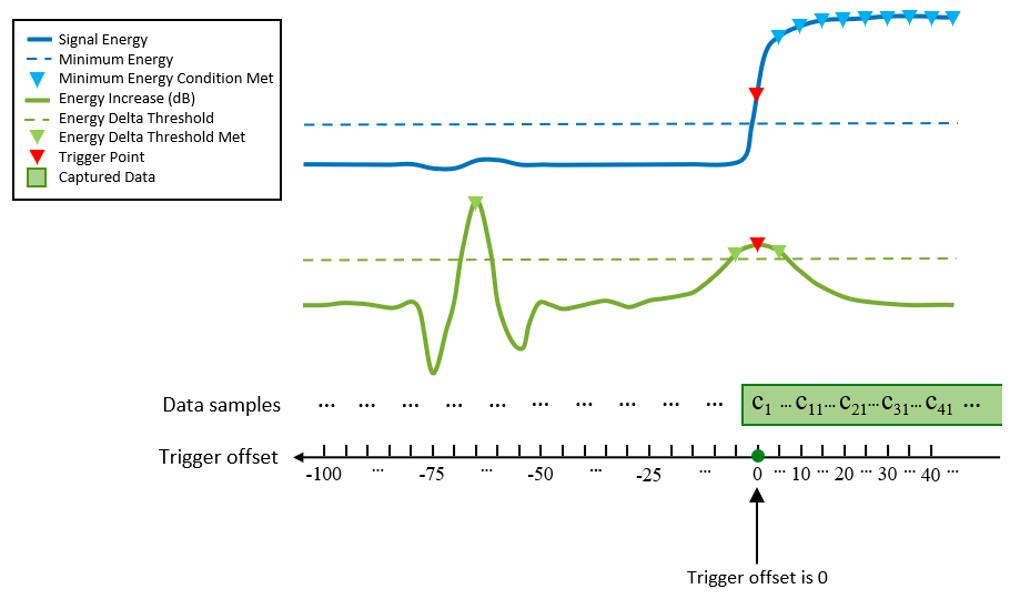
By default, data capture starts at the trigger point. To adjust the
start of the data capture relative to the trigger point, use the
TriggerOffset property. For example, this figure shows a
scenario in which the trigger offset is 0. Therefore, data capture
starts at the first detection point.

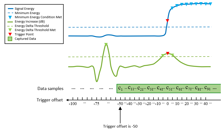
In this second scenario, the trigger point is the same, but the trigger offset is –50. Therefore, data capture starts at the specified trigger offset.

Version History
Introduced in R2023bYou can now use a radio object as the radio input argument when you
create a energyDetector object.
The capture object function can now capture multiple
consecutive signals with an energyDetector object. Set the
TimestampUnit property to
"sample-clock-cycle" to return the capture function output argument timestamp as an integer number of sample clock
cycles.
See Also
Functions
Objects
MATLAB Command
You clicked a link that corresponds to this MATLAB command:
Run the command by entering it in the MATLAB Command Window. Web browsers do not support MATLAB commands.
Select a Web Site
Choose a web site to get translated content where available and see local events and offers. Based on your location, we recommend that you select: .
You can also select a web site from the following list
How to Get Best Site Performance
Select the China site (in Chinese or English) for best site performance. Other MathWorks country sites are not optimized for visits from your location.
Americas
- América Latina (Español)
- Canada (English)
- United States (English)
Europe
- Belgium (English)
- Denmark (English)
- Deutschland (Deutsch)
- España (Español)
- Finland (English)
- France (Français)
- Ireland (English)
- Italia (Italiano)
- Luxembourg (English)
- Netherlands (English)
- Norway (English)
- Österreich (Deutsch)
- Portugal (English)
- Sweden (English)
- Switzerland
- United Kingdom (English)