WLAN HDL Transmitter
This example shows how to implement a wireless local area network (WLAN) transmitter for a single-input and single-output (SISO) design. This example generates an IEEE® 802.11a/n/ac™ standard WLAN-baseband waveform supporting orthogonal frequency division multiplexing (OFDM) modulation. The Simulink® model in this example is optimized for HDL code generation and hardware implementation.
This example supports non-high-throughput (non-HT), high-throughput (HT), and very-high-throughput (VHT) frame formats for the 20 MHz channel bandwidth option, long guard interval, and binary convolutional coding (BCC) channel encoding for the WLAN packet transmission. For more information on the WLAN frame formats and frame structure, see WLAN PPDU Structure (WLAN Toolbox). The WLAN packet includes a preamble field with a short-training field (STF), long-training field (LTF), signal fields, data field, and idle time samples. You specify a modulation and coding scheme (MCS) and frame format as inputs to the model in this example along with input bytes of size equal to physical layer conformance procedure service data unit (PSDU) length.
Model Architecture
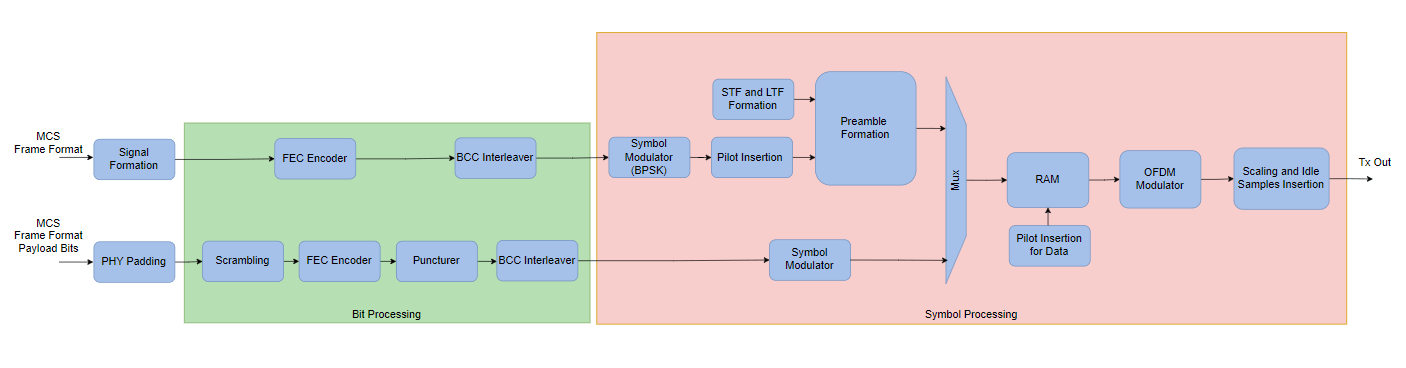
This figure shows the high-level architecture of the WLAN transmitter. Based on the input MCS and frame format for the WLAN packet, the model generates the corresponding preamble component and prepends it to the data component.
Lookup tables(LUTs) provide the STF and LTF symbols. Bit processing modules such as the convolutional encoder and the interleaver process the generated signal bits. Symbol modulator maps the interleaved bits to symbols. The frame format determines the locations at which the model adds pilot symbols to form the signal symbols.
The model pads the valid input data bits with service, tail, and pad bits. A scrambler, initialized to 93, scrambles the padded bits. The scrambled bits undergo convolutional encoding at 1/2 rate and are punctured according to the input MCS code rate. A serializer serializes these punctured bits, followed by interleaving and symbol modulation.
The model stores the pilot-inserted preamble and the non-pilot-inserted data symbols in a random access memory (RAM) and reads them based on the ready signal output from the OFDM Modulator block. Before OFDM modulation, the model inserts pilot symbols for the data symbols at the respective pilot locations. The model then scales the OFDM modulated data according to the number of active subcarriers in each OFDM symbol. After each WLAN packet, the model adds idle time samples with a value of zero.
Transmitter Interface
The wlanhdlTransmitter model shows the wlanHDLTx subsystem and its interface.
modelname = 'wlanhdlTransmitter';
open_system(modelname);
![]()
Model Inputs:
MCS — Modulation and coding scheme, specified as a ufix3 scalar. This port accepts values starting from
0to7, which support the BPSK, QPSK, 16-QAM, and 64-QAM modulation types with different code rates.
frameFormat — Frame format for the WLAN packet, specified as a ufix2 scalar. This port accepts values
0,1, and2, which correspond to non-HT, HT-MF, and VHT respectively.
bitIn — Input payload data of PSDU length bytes, specified as a Boolean scalar.
validIn — Valid signal for the input data, specified as a Boolean scalar.
start — Start signal to start the WLAN packet transmission, specified as a Boolean scalar.
Model Outputs:
txData — Transmitter output, returned as a complex scalar with fixdt(1,16,13) datatype sampled at 20 Msps.
txValid — Control signal that validates the transmitter output, returned as a Boolean scalar sampled at 20 Msps.
ready — Control signal that indicates when to sample the input payload, MCS, and frame format input values, returned as a Boolean scalar.
Transmitter Structure
The wlanHDLTx subsystem generates a WLAN packet by processing the input signals at multiple stages.
wlanHDLTx
open_system([modelname '/wlanHDLTx'],'force');
![]()
Preamble and Data Symbol Formation
The Preamble and Data Symbol Formation subsystem includes the Preamble Symbols and Data Symbols subsystems. The Preamble Symbols subsystem outputs the pilot-inserted preamble symbols and the Data Symbols subsystem outputs the non-pilot-inserted data symbols.
open_system([modelname '/wlanHDLTx/Preamble and Data Symbol Formation'],'force');
![]()
Preamble Symbols
The Preamble Symbols subsystem generates the pilot-inserted preamble symbols based on the input frame format. For the non-HT frame format, this subsystem output contains the L-STF, L-LTF, and L-SIG symbols. For the HT-MF frame format, this subsystem output contains L-STF, L-LTF, L-SIG, HT-SIG, HT-STF, and HT-LTF symbols. For the VHT frame format, the subsystem output contains L-STF, L-LTF, L-SIG, VHT-SIGA, VHT-STF, VHT-LTF, and VHT-SIGB symbols. This subsystem includes the STFLTFFormation, signalBitsFormation, and signalFieldProcessing subsystems. The STFLTFFormation subsystem reads the STF and LTF symbols from the RAMs and places them according to the frame format. The signalBitsFormation subsystem generates signal field bits based on the input MCS, frame format, PSDU length, and the computed number of data OFDM symbols. The signalFieldProcessing subsystem encodes these bits with 1/2 rate, interleaves, symbol modulates, and adds the pilot symbols at the respective pilot locations corresponding to each signal symbol. It multiplexes the STFs, LTFs, and signal symbols to form the preamble component for the respective input frame format.
open_system([modelname '/wlanHDLTx/Preamble and Data Symbol Formation/Preamble Symbols'],'force');
![]()
Data Symbols
The Data Symbols subsystem adds service, tail, and pad bits to the input data bits and then scrambles the input data bits in the Scrambler subsystem with the example state in Section 1.1.5.2 of [ 1 ]. The BCC Encoder subsystem convolutional encodes the data with 1/2 rate and punctures the encoded data according to the code rate of the input MCS value. A Serializer1D (HDL Coder) is used to serialize the data bits after BCC encoding. The Symbol Interleaver subsystem interleaves the data bits based on the MCS value. The Symbol Modulator forms symbols from the interleaved bits based on the MCS.
open_system([modelname '/wlanHDLTx/Preamble and Data Symbol Formation/Data Symbols'],'force');
![]()
Multiplexer
The Multiplexer subsystem multiplexes the preamble and data symbols to perform OFDM modulation. This subsystem computes the total number of symbols, total number of OFDM symbols, and the total packet length from the number of preamble symbols, the number of data symbols, the number of preamble OFDM symbols, the number of data OFDM symbols, and the idle time samples for each packet.
OFDM Symbol Formation
The OFDM Symbol Formation subsystem writes the multiplexed preamble (pilot-inserted) and data (non-pilot-inserted) symbols into memory for each packet at bit rate. The ready signal of the OFDM Modulator block triggers the reading of data from the memory at symbol rate. While reading from the first RAM, the system sets the output ready signal to high to accept input data bits for processing and stores the processed bits in the second RAM. The Read Address Generation and Pilot Insertion subsystem generates the read address for the RAMs and adds the pilots at the respective locations for the data symbols based on the frame format.
open_system([modelname '/wlanHDLTx/OFDM Symbol Formation'],'force');
![]()
OFDM Modulation
The OFDM Modulation subsystem has the OFDM Mod Parameters MATLAB function block and the OFDM Modulator block. The OFDM Mod Parameters MATLAB function block generates the OFDM parameters for each OFDM symbol and the OFDM Modulator block performs the OFDM modulation.
open_system([modelname '/wlanHDLTx/OFDM Modulation'],'force');
![]()
Scaling and Adding Idle Time Samples
The Scaling and Idle time Addition subsystem performs scaling on the OFDM symbols based on the active subcarriers in each OFDM symbol and adds the idle time samples after each WLAN packet.
open_system([modelname '/wlanHDLTx/Scaling and Idle Time Addition'],'force');
![]()
Ready Generation
The Ready Generation subsystem generates a ready signal to accept the MCS, frame format, and valid bits as inputs. This subsystem accepts the start, wrDonePulse, and rdDonePulse as inputs. The start and wrDonePulse trigger the generation of the ready signal for the first two packets and the rdDonePulse triggers the generation of the ready signal for the next packets.
Run Transmitter
Run the runWLANTransmitter MATLAB script to generate the input bits and specify MCS, frame format, number of packets, PSDU or APEP length, and idle time between packets. This script runs the WLAN transmitter model, verifies and compares the model outputs with wlanWaveformGenerator (WLAN Toolbox) function from the WLAN Toolbox™.
runWLANTransmitter
Compare Transmitter output
SQNR in dB: real 66.5774 imag 66.7889
![]()
![]()
![]()
HDL Code Generation and Implementation Results
To generate HDL code for this example, you must have an HDL Coder™ license. Run the runWLANTransmitter script and use makehdl and makehdltb commands to generate HDL code and HDL testbench for the wlanHDLTx subsystem. The testbench generation time depends on the simulation time.
You can synthesize the generated HDL code and target on the Xilinx® Zynq® Ultrascale+ RFSoC ZCU111 evaluation board. The table shows the post place and route resource usage results. The design meets timing with a clock frequency of 330 MHz.
F = table(...
    categorical({'Slice LUT'; 'Slice Registers'; 'RAMB36'; 'RAMB18';...
    'DSP48'}),...
    categorical({'8145'; '10818'; '73'; '8'; '23'}),...
    'VariableNames',...
    {'Resources','Usage'});

disp(F);
       Resources       Usage
    _______________    _____

    Slice LUT          8145
    Slice Registers    10818
    RAMB36             73
    RAMB18             8
    DSP48              23
References
IEEE 802.11-2016 - IEEE Standard for Information technology--Telecommunications and information exchange between systems Local and metropolitan area networks--Specific requirements - Part 11: Wireless LAN Medium Access Control (MAC) and Physical Layer (PHY) Specifications.
See Also
Blocks
- OFDM Modulator | Puncturer | Convolutional Encoder | Serializer1D (HDL Coder) | Symbol Modulator
Functions
wlanWaveformGenerator(WLAN Toolbox)