Main Content

Serializer1D

Convert vector signal to scalar or smaller vectors

  • Serializer1D block

Libraries:
HDL Coder / HDL Operations

Description

The Serializer1D block converts a slower vector signal into a faster stream of scalar signals or smaller size vector signals based on the Ratio and Idle Cycle values. To match the faster serialized output, the sample time changes according to this equation:

Output Sample Time=Input Sample Time/(Ratio+Idle Cycles)

Consider this example where the input data is a vector of size 4 and the Ratio is set to 4.

Timing Diagram of the Input and Output of the Serializer Block

The output data serializes each of the vector signals into four scalar signals. The sample time at the output is: Output Sample Time=Input Sample Time/4.

To add idle cycles at the end of each output, for Idle Cycles, specify an integer greater than zero. Consider this example with Ratio set to 4 and Idle Cycles set to 2.
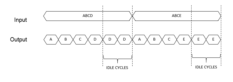
Timing Diagram of the Input and Output of the Serializer Block with Idle Cycles

For each slow vector signal, the output has six fast cycles consisting of the four serialized scalar signals and two idle cycles. The sample time at the output is Output Sample Time=Input Sample Time/6.

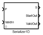
The Serializer1D block provides three control signals: ValidIn, ValidOut, and StartOut. You can use ValidIn to control ValidOut and StartOut. The serialized output does not depend on ValidIn. To determine whether the output serialized data is valid, use ValidIn and ValidOut. If you give a high input to ValidIn, and there are no idle cycles, ValidOut gives a high output, which indicates that the output serialized data is valid.

Consider an example that has input data as a vector of size 4, Ratio set to 4, Idle Cycles set to 2, and uses all three control signals.

Timing Diagram of the Input and Output of the Serializer Block with Idle Cycles and three control signals

For the first input vector, ABCD, ValidIn is false. StartOut and ValidOut become false. This means that the output data values are not valid. In the waveform, the data values are represented as X, which correspond to don’t care values.

For the second input vector, ABCE, ValidIn is true. The output data serializes the vector into four scalar signals. The control signal StartOut becomes true at output A to indicate the start of serialization. In the next cycle, the StartOut signal becomes false. ValidOut is true for all four output signals indicating valid output data for the four cycles. ValidOut becomes false for the idle cycles, and the output data values are don’t care values.
Ports

Input

expand all

Input signal to serialize. Bus data types are not supported.

Data Types: single | double | half | int8 | int16 | int32 | int64 | uint8 | uint16 | uint32 | uint64 | Boolean | fixed point | enumerated

Input control signal that indicates valid input signal. This port is available when you select the ValidIn check box.

Data Types: Boolean

Output

expand all

Serialized output signal. Bus data types are not supported.

Data Types: single | double | int8 | int16 | int32 | int64 | uint8 | uint16 | uint32 | uint64 | Boolean | fixed point | enumerated

Output control signal that indicates the start of serialization. You can use this signal as the StartIn input to the Deserializer1D block. To use this port, select the StartOut check box.

Data Types: Boolean

Output control signal that indicates valid output signal. You can use this signal as the ValidIn input to the Deserializer1D block. This port is available when you select the ValidOut check box.

Data Types: Boolean

Parameters

expand all

Serialization factor, specified as a positive scalar.

The ratio is equal to the size of the input vector divided by the size of the output vector. Input vector size must be divisible by the ratio.

Enter the number of idle cycles added at the end of each output.

Select to activate the StartIn port.

Select to activate the ValidIn port.

Select to activate ValidOut port.

Size of the input data signal. Input vector size must be divisible by the ratio. By default, the block inherits size based on the context within the model.

Time interval between sample time hits, or another appropriate sample time such as continuous. By default, the block inherits sample time based on context within the model. For more information, see Sample Time.

Input signal type of the block, specified as auto, real, or complex. Default is auto.

Extended Capabilities

C/C++ Code Generation
Generate C and C++ code using Simulink® Coder™.

Version History

Introduced in R2014b

expand all