Change Image Size
This example shows how to downsample a multicomponent image by using the Image Resizer block. The example also shows how to implement custom bicubic and Lanczos-2 interpolation algorithms for FPGAs by using basic Simulink blocks.
The most basic of interpolation algorithms, nearest neighbor, assumes the value of its closest neighbor and is computationally lightweight. In theory, you can achieve a more exact reconstruction of an image by using a sinc kernel. However, sinc kernels have infinite spatial extent. To limit the extent, interpolation implementations use simpler kernels to approximate a sinc. The bilinear interpolation algorithm uses the weighted sum of the nearest four pixels to determine the values of the output pixels. Bicubic and Lanczos-2 interpolations are approximations of a sinc kernel. Bicubic interpolation is a more computationally efficient version of the Lanczos-2 method. This example implements and compares these interpolation algorithms.
Behavioral Reference
By default, the imresize function uses the bicubic interpolation algorithm. You can choose the nearest neighbor, bilinear, or Lanczos-2 interpolation algorithms by setting the 'Method' name-value argument to 'nearest', 'bilinear', or 'lanczos2', respectively.
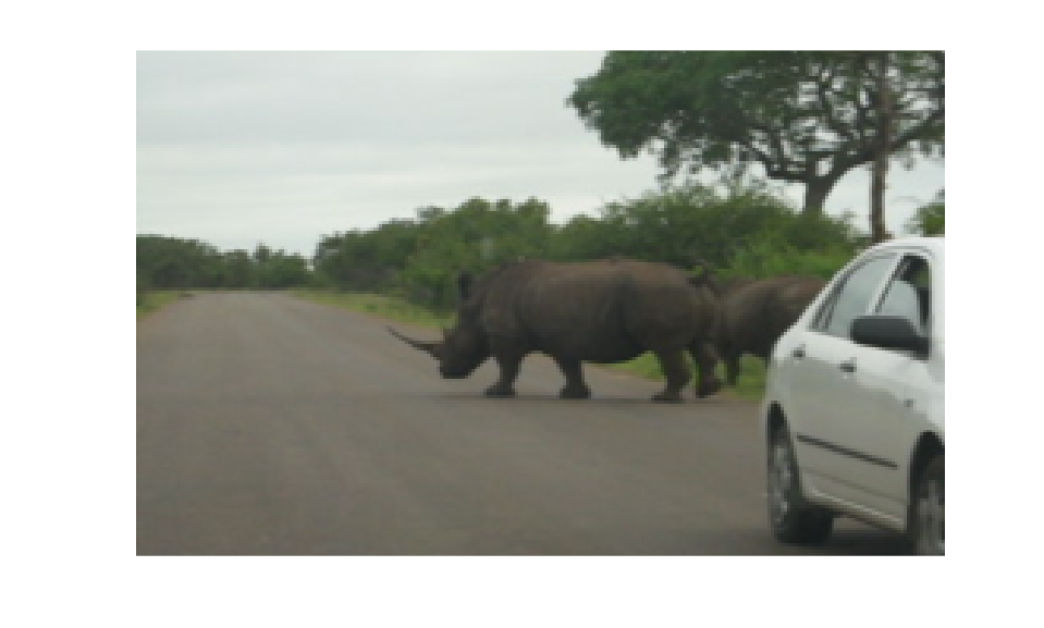
v = VideoReader('rhinos.avi');
I = readFrame(v);
Y = imresize(I,[160,256],Method='bilinear');
figure;
imshow(Y)
Interpolation Algorithms
Nearest Neighbor
Nearest neighbor interpolation determines the inserted pixel values by assuming the value of the closest of its four neighbors. The interpolator calculates the horizontal,  , and vertical,
  , scale factors independently.
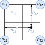
No additional calculations are required once the scale has been determined, which removes the requirement for any multipliers.
Bilinear and Bicubic
Bilinear interpolation, a first-order sinc approximation algorithm, determines the inserted pixel value from the weighted average of the four input pixels nearest to the inserted location.
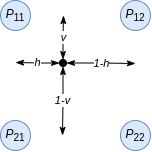
The value for each output pixel is given by  .
.
The bicubic algorithm [1] calculates the average of the 16 input pixels nearest to the inserted location.
The bicubic coefficients are given by 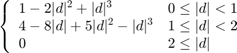 .
.
These equations show that the bilinear and bicubic algorithms calculate coefficients for each output pixel.
Lanczos-2
The Lanczos-2 algorithm precalculates the coefficients based on the resize factor. The model calls the lanczos2_coeffi.m script to calculate and store these coefficients. The script calculates the Lanczos-2 coefficients using 6 taps and 32 phases.
Implementation of Basic-Blocks Interpolation Algorithms for HDL
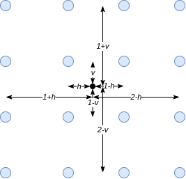
This figure shows the principle used to implement the image resize algorithm for hardware. For example, consider resizing an image by a scale factor of 3/4. One possible implementation is to upsample by a factor of 3 and then downsample by a factor of 4. The figure shows the pixel indexes after these operations. Blue dots represent the original pixels, and green crosses represent the interpolated pixels after upsampling.
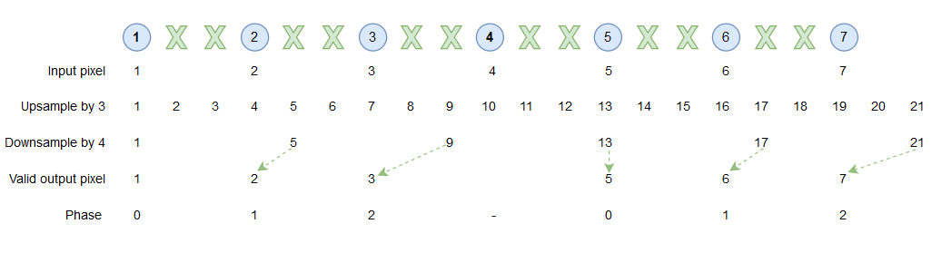
The indexes after downsampling show that not all the interpolated pixels are used in the output image. This example implements a more efficient version of the downsample step by generating interpolated pixels only when they are needed in the output image.
The phase, shown in the bottom line of the figure, is an index that selects which pixels are needed for the output image. When the phase is 0, the algorithm returns the original input pixel value. When the phase is 1, the algorithm calculates coefficients to generate the interpolated pixel in the first position. When the phase is 2, the algorithm calculates coefficients to generate the interpolated pixel in the second position.
Example Model
The model contains two datapaths. The top datapath uses the Image Resizer block to perform resize using bilinear interpolation. The bottom datapath implements resize using bicubic and Lanczos-2 interpolation.

Image Resizer
The Image Resizer block provides support for nearest neighbor and bilinear interpolation with an integrated antialiasing prefilter.
The integrated lowpass Gaussian antialiasing filter provides convenient means to avoid aliasing introduced through the reduction in sampling rate when downsampling.
The Image Resizer block provides the ability to insert horizontal blanking between output active video lines. You can use this capability to meet downstream horizontal blanking constraints. However, do not use this capability to perform the role of the Pixel Stream FIFO, which buffers input video lines to output contiguous valid active video lines. Inserting too much horizontal blanking can have an impact on the overall frame rate and may necessitate pacing of the input.
The model includes an optional Pixel Stream FIFO after the Image Resizer block that you can use to consolidate the output pixels, while the Measure Timing block displays the size of the output frames.
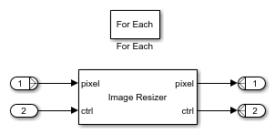
When processing multicomponent data, use the Image Resizer block with a ForEach subsystem. The ForEach subsystem replicates the Image Resizer block across each input component while maintaining a single multicomponent frame input and output.
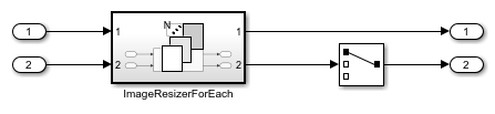
The ForEach subsystem is configured to partition and concatenate the pixel input and output on the second dimension, horizontally. The output pixelcontrol buses are all duplicates and so only one needs to be retained at the top level. The Selector block selects a single pixelcontrol bus to use in the rest of the data path.
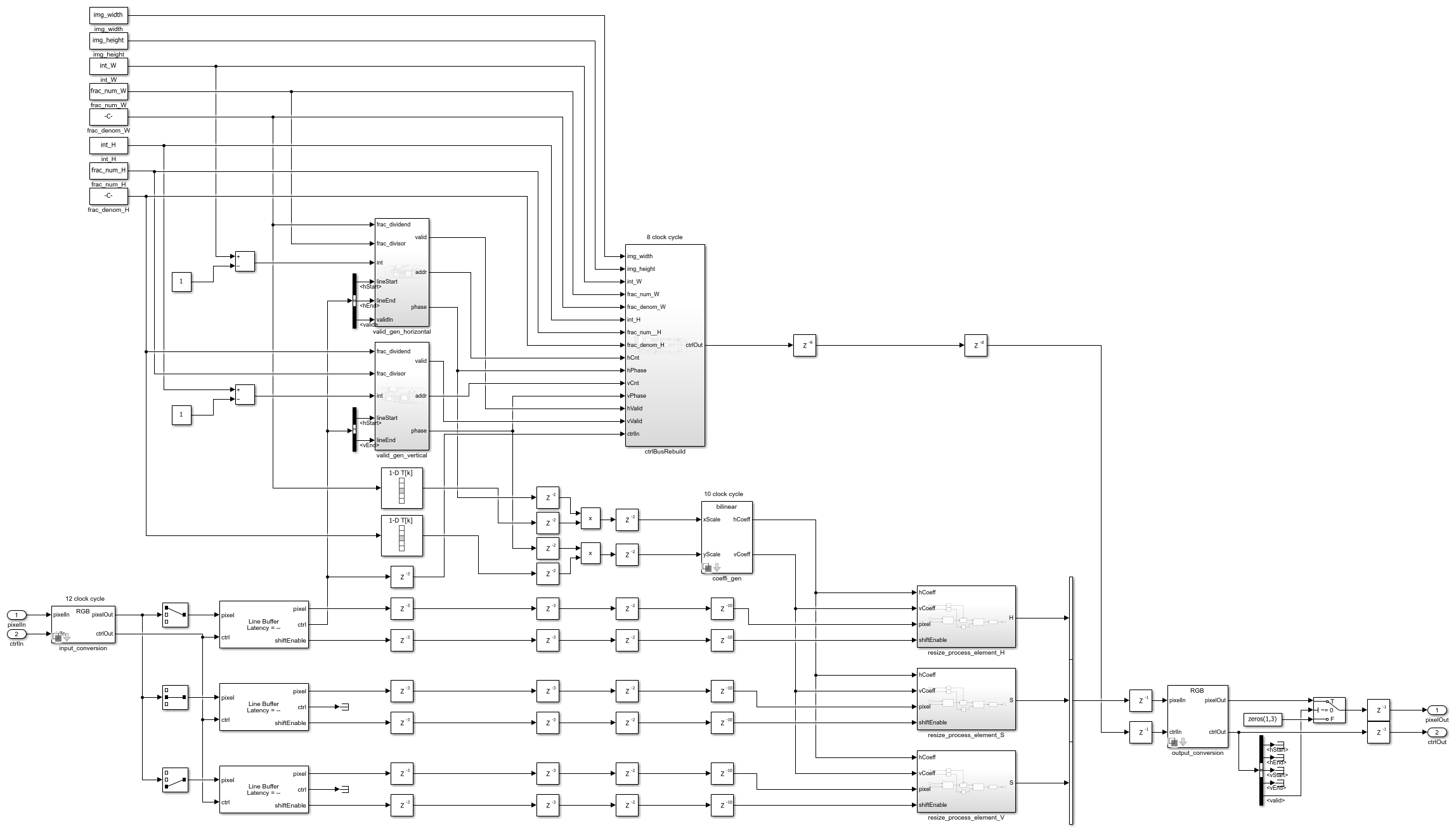
Basic-Blocks Implementation
Similar to the imresize function, the imresize(downsample) subsystem in this model supports two ways to define the output image size. You can specify a scale factor ranging from 1.000 to 127.999, or you can define the output frame width and height in pixels down to a minimum of 8 by 8. Double-click the imresize(downsample) subsystem to set its parameters. The imresize(downsample) subsystem requires contiguous video lines.
To avoid aliasing with the basic-blocks implementation, the model includes a lowpass filter before the imresize(downsample) subsystem that you can enable by setting its Constant block input to a value of 1. After the imresize(downsample) subsystem, there is also an optional Pixel Stream FIFO and a Measure Timing block to display its output frame sizes.
In the imresize(downsample) subsystem, the input_conversion and output_conversion subsystems convert the color space [2] of the pixel stream based on the parameter on the mask. The valid_gen_horizontal and valid_gen_vertical subsystems return control signals that are used for generating coefficients and rebuilding the output control bus. If the last line of the image contains no valid pixels after downsampling, the ctrlBusRebuild subsystem rebuilds the control bus for the new size.
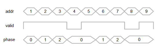
This diagram shows the expected output from the valid_gen_horizontal and valid_gen_vertical subsystems. The valid signal indicates the validity of the current address and the corresponding phase. To simplify rebuilding the control bus, the first line and row of each output frame are always valid.
The coefficient generation subsystem, coeffi_gen, is a variant subsystem, where bilinear, bicubic, and Lanczos-2 coefficient generators are implemented separately. You can select the algorithm from the mask.

The resize_process_element subsystems multiply the coefficients with each pixel component by using a separable filter in vertical order and then in horizontal order. The trim_0_1 subsystem ensures the result is between 0 and 1.

Resource Usage
These tables show the resource usage for the Image Resizer block and imresize(downsample) subsystem with 240p video input, and do not include the antialiasing filters or the Pixel Stream FIFOs. The design was synthesized to achieve a clock frequency of 150 MHz.
This table shows the resources for each of the algorithms when downsampled in the RGB color space.
                                        LUT     LUTRAM     FF      BRAM    DSP
                                        ____    ______    _____    ____    ___

    Image Resizer - Nearest Neighbor    1282      36       1337      3      0
    Image Resizer - Bilinear            1317      24       1808      3     12
    imresize(downsample) - Bilinear     2414     386       4333    1.5     20
    imresize(downsample) - Bicubic      4405     597       8827    4.5     30
    imresize(downsample) - Lanczos-2    6490     802      13708    7.5     38
This table shows the resources for each of the three imresize(downsample) algorithms when downsampled in the HSV color space.
                                        LUT     LUTRAM     FF      BRAM    DSP
                                        ____    ______    _____    ____    ___

    imresize(downsample) - Bilinear     2987     444       5688     11     26
    imresize(downsample) - Bicubic      5117     658      10248     14     36
    imresize(downsample) - Lanczos-2    7139     875      15351     17     44
References
[1] Keys, R. "Cubic Convolution Interpolation for Digital Image Processing." IEEE Transactions on Acoustics, Speech, and Signal Processing 29, no. 6 (December 1981): 1153-60. https://doi.org/10.1109/TASSP.1981.1163711.
[2] Smith, Alvy Ray. "Color Gamut Transform Pairs." In Proceedings of the 5th Annual Conference on Computer Graphics and Interactive Techniques - SIGGRAPH '78, 12-19. Not Known: ACM Press, 1978. https://doi.org/10.1145/800248.807361.