Scene Interrogation in 3D Environment
Note
Simulating models in the 3D visualization environment requires Simulink® 3D Animation™.
The scene interrogation with camera and ray tracing reference application provides the Simulink interface with the 3D visualization environment. Before simulating the reference application:
Ensure that your system meets the minimum hardware requirements. For more information, see Unreal Engine Simulation Environment Requirements and Limitations.
Install the Virtual Mcity scene. For more information, see Virtual Mcity.
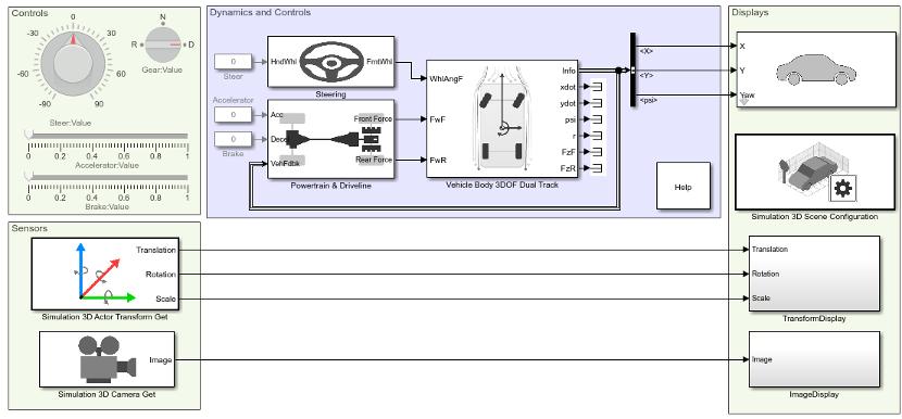
The scene interrogation with camera and ray tracing reference application contains:
One passenger vehicle with a simple driveline, combined slip wheel, and 3DOF vehicle dynamics model.
One camera mounted on the passenger vehicle rear-view mirror.
Steering, acceleration, gear, and braking controls.
Vehicle light controls.
3D visualization environment configured for the Virtual Mcity scene.
Create and open a working copy of the camera and ray tracing reference application project.
When you run the simulation, the reference application provides this vehicle and scene information.
| Window | Description | ||||||||||||||||||||||||||||||||||
|---|---|---|---|---|---|---|---|---|---|---|---|---|---|---|---|---|---|---|---|---|---|---|---|---|---|---|---|---|---|---|---|---|---|---|---|
Simulation 3D Viewer | Video output of the Unreal Engine® 3D visualization environment image feedback. By
default, the display shows the view from the Simulation 3D
Scene Configuration block Scene
view parameter
To smoothly change the camera views, use these keyboard shortcuts.
For additional camera controls, use these keyboard shortcuts.
| ||||||||||||||||||||||||||||||||||
SDL Video Display | Video image output of Simulation 3D Camera Get block. By default, the display shows the view specified by these parameter settings:
| ||||||||||||||||||||||||||||||||||


This table summarizes the parts of the reference application.
| Name | Description |
|---|---|
Controls | Dials and gauges that control the vehicle steering, gear, acceleration, and braking. The braking control turns on the vehicle brake lights. Setting the gear control to R turns on the vehicle reverse lights. |
Sensors | The Simulation 3D Actor Transform Get block returns the translation, rotation, and scale for the vehicle passenger vehicle and four wheels from the 3D visualization environment. The Simulation 3D Camera Get block returns the camera image from the 3D visualization environment. By default, the block returns image data for a camera location specified by these parameter settings:
|
Dynamics and Controls | Interfaces with Simulink to calculate the dynamic response of the vehicle plant and controller. By default, the subsystem contains a simple driveline and the Vehicle 3DOF Dual Track block vehicle dynamics model. Implements a Light Controls subsystem that you can use to control the headlights and signal lights. |
Displays | The Simulation 3D Vehicle with Ground Following block implements a passenger vehicle in the 3D visualization environment. The block uses the vehicle position to adjust the vehicle elevation, roll, and pitch so that the vehicle follows the ground terrain. By default, the block has these parameter settings:
The Simulation 3D Scene Configuration block configures the Unreal Engine 3D visualization environment. By default, the block has these parameter settings:
The TransformDisplay
subsystem displays the translation, rotation, and scale of the
The ImageDisplay subsystem displays the video image output of Simulation 3D Camera Get block in the SDL Video Display window. |
Displays Subsystems
TransformDisplay Subsystem
In the TransformDisplay subsystem, the Display block provides the translation, rotation, and scale of the vehicle body and four wheels. Use the Constant block value to control the display.
1— Translation2— Rotation3— Scale
For example, to display translation information, set the value to
1.
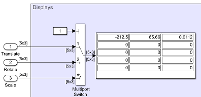
The display indicates that the:
Vehicle body is at
-212.5m,65.66m, and0.0112m along the world X-, Y-, and Z- axes, respectively.Wheels are at their initial positions along the world X-, Y-, and Z- axes, respectively.
The Display block provides an array of the vehicle and wheel locations.
Vehicle translation and rotation are along the world coordinate system axes.
Wheel translations and rotations are with respect to their initial positions, along the world coordinate system axes.
ImageDisplay Subsystem
In the ImageDisplay subsystem, the Level-2 MATLAB S-Function block
uses the VideoDisplayMSfcnWin function to display the video image
output of Simulation 3D Camera Get block.
See Also
Simulation 3D Actor Transform Get | Simulation 3D Camera Get | Simulation 3D Scene Configuration | Virtual Mcity | Simulation 3D Vehicle with Ground Following
Topics
- Scene Interrogation with Camera and Ray Tracing Reference Application
- Send and Receive Double-Lane Change Scene Data
- 3D Scenes for Simulation in Unreal Engine Environment
- Coordinate Systems in Vehicle Dynamics Blockset
- Customize 3D Scenes for Vehicle Dynamics Simulations
- How Unreal Engine Simulation for Vehicle Dynamics Blockset Works