Speedgoat and Simulink Real-Time Setup
This topic helps you with setting up Speedgoat® and Simulink® Real-Time™ for PX4 Autopilot in Hardware-in-the-Loop (HITL) Simulation with Speedgoat in Simulink example. Hardware-in-the-loop simulation allows you to validate your controller design code running on an embedded system in normal and adverse real-world conditions.
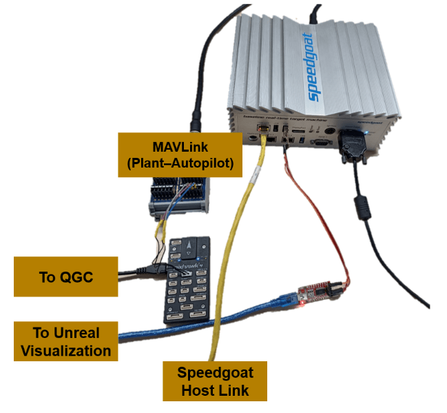
The following image shows an overview of hardware connections and information flow between PX4® Autopilot, Speedgoat, and QGC.

In the PX4 Autopilot in Hardware-in-the-Loop (HITL) Simulation with Speedgoat in Simulink example, a quadcopter plant model, along with its sensors, are modeled in Simulink. The generated code is deployed to Speedgoat Real-Time Target machines to perform HITL simulation. The example demonstrates the following workflows.
Real-Time simulation of plant and sensors in Speedgoat.
Controller deployment to PX4 Autopilot.
Photorealistic simulation using unreal engine, based on plant states obtained from Speedgoat.
Running an obstacle avoidance algorithm on Jetson™ using the depth camera data simulated in Unreal Engine.
The plant model communicates with PX4 Autopilot to share the sensor and actuator data. The plant model additionally shares the UAV ground truth (position and orientation) to host PC running photorealistic simulation.
The photorealistic simulator provides a 3D visualization of the UAV’s movement along with simulating its depth camera. Depth data is sent over to a Jetson onboard computer running an obstacle avoidance algorithm, which corrects the path accounting for any obstacles and sends back corrected path over to PX4 Autopilot.
Required Hardware
To run this example, you will need the following hardware:
Speedgoat Baseline with IO397 module
IO397 Terminal board
A supported PX4 Autopilot board with a class 10 microSD card.
Micro USB (Universal Serial Bus) type-B cable
USB to Ethernet converter
Pixhawk® UART to jumper male converter
2 x FTDI units
To run onboard obstacle avoidance, you need the following,
Jetson Xavier / Nano connected to autopilot over UART
Make Connections for Speedgoat
Connect the hardware as shown in this diagram. You can skip the Jetson connection if you are not running onboard obstacle avoidance.

A sample image of Speedgoat connected to PX4 Autopilot, QGC, host computer is shown below.
Connect the following ports between Pixhawk and Speedgoat's IO397 Terminal board.
Pixhawk Speedgoat connections
| Pixhawk (GPS) | IO397 Terminal board |
|---|---|
| Tx | 16b |
| Rx | 15b |
| GND | 17b |
Pixhawk GPS 1 port is connected to IO397 Terminal board.
To establish a connection with unreal visualization model, perform these steps.
connect a FTDI port to the right USB port.
Connect the TX of FTDI to RX of another FTDI and vice-versa. Also connect gnd.
Connect the second FTDI unit to host PC that runs unreal visualization model.
Speedgoat Configuration
To configure the Serial ports and IO397 module, refer to the following image. If you have a different Speedgoat configuration such as a different IO module, then use this information to configure Speedgoat. Serial ports and IO397 modules are available in Speedgoat Setup section of Simulink plant model (UAV_Dynamics_Speedgoat). For more information on opening the Simulink model, see PX4 Autopilot in Hardware-in-the-Loop (HITL) Simulation with Speedgoat in Simulink.

Software Setup
Along with the required products mentioned in the example, you must also download and install the following software.
Simulink IO Blockset
IO397 Configuration package (The example uses v4.1)
Create an account in Speedgoat to download and install the Simulink IO Blockset and IO397 configuration package.
For more information, see Speedgoat Software.
Connections for Speedgoat
Connect the Speedgoat machine to host computer over an Ethernet-USB converter.
Depending on the operating system installed on the host computer, use the links provided below to configure your network adapter to communicate with Speedgoat.
For Windows: Enable Development Computer Communication (Windows) (Simulink Real-Time)
For Linux: Enable Development Computer Communication (Linux) (Simulink Real-Time)
Open
slrtExplorerand configure the IP address and update the Speeedgoat firmware. For more details, see the Configure Target, Update, and Reboot (Simulink Real-Time) example.If you are not yet connected to the target computer, click Disconnected to change it to Connected.
PX4 Parameter Setup in QGC
Set the parameters values in QGroundControl (QGC), as shown in the table below.
QGC Parameters
| Parameter | Value |
|---|---|
SER_GPS1_BAUD | 921600 8N1 |
SER_TEL1_BAUD | 230400 8N1 |
MAV_0_CONFIG | TELEM 1 |
MAV_0_FORWARD | 1 |
MAV_0_MODE | Onboard |
MAV_0_RADIO_CTL | 1 |
MAV_0_RATE | 1200 B/s |
MAV_1_CONFIG | GPS1 |
MAV_1_FORWARD | 0 |
MAV_1_MODE | Config |
MAV_1_RATE | 0 B/s |
See Also
PX4 Autopilot in Hardware-in-the-Loop (HITL) Simulation with Speedgoat in Simulink