Convert PX4 PWM Output Block to PX4 Actuator Write Block
The PX4 PWM Output block will be removed in a future release. It is recommended to use the PX4 Actuator Write block as a replacement. To convert existing PX4 PWM Output blocks in your Simulink model to PX4 Actuator Write blocks, follow the steps listed in this section.
The key difference between these blocks is in the input value range and type. For the
PX4 PWM Output, inputs are PWM on-time values with a
uint16 type. However, the PX4 Actuator Write block
requires inputs to be normalized values of type single, within a range of
[0, 1] for motors and [-1, 1] for servos.
To convert the block, perform these steps:
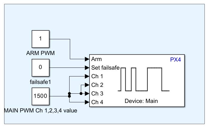
Open your Simulink model that includes the PX4 PWM Output block. Here is an example model with an ARM PWM signal, failsafe, and four MAIN PWM channels connected to PWM Output block.

Select the PX4 PWM Output block and press the Delete key on your keyboard to remove it.
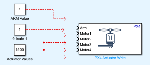
Add a PX4 Actuator Write block into your model and establish the necessary connections.

Link the ARM PWM signal to the Arm input of the PX4 Actuator Write block.
Remove the failsafe signal, as it is not used by the PX4 Actuator Write block.
Adjust the MAIN PWM signal values. For the minimum and maximum values from
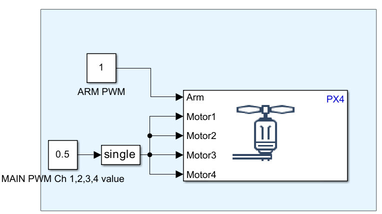
1000to2000, the corresponding actuator values will range from0to1. So for the value1500, actuator value will be0.5.
Map the PWM Output block channels to the Motors inputs on the Actuator Write block. Since the Motors inputs only accept Single scalar values, insert a Data Type Conversion block to modify the channel values accordingly.

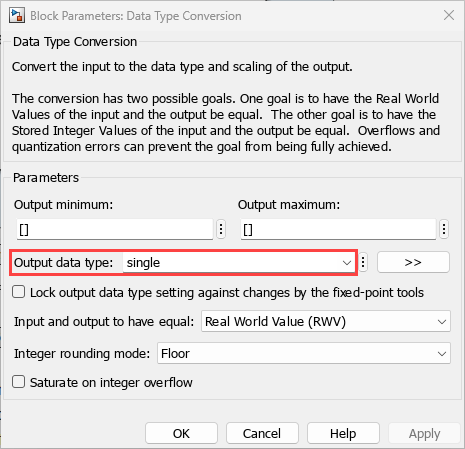
Open the Data Type Conversion block settings by double-clicking it. In the Block Parameters dialog, set the Output data type to
single, then click Apply and OK.
Your model should now reflect the changes, with the PX4 PWM Output block successfully converted to a PX4 Actuator Write block.