Getting Started with PX4 Write Parameter Block
This example shows you how to use the PX4 Write Parameter block to write parameters values to a PX4-based flight controller. This allows you to dynamically change flight parameters during simulation and deployment, enabling real-time tuning and configuration.
Prerequisites
If you are new to Simulink, watch the Simulink Quick Start video.
Perform the initial Setup and Configuration of the support package using Hardware Setup screens.
Required Third-Party Software
Recommended: QGC version 4.3.0
Model
Open the px4WriteCustomParameter model.
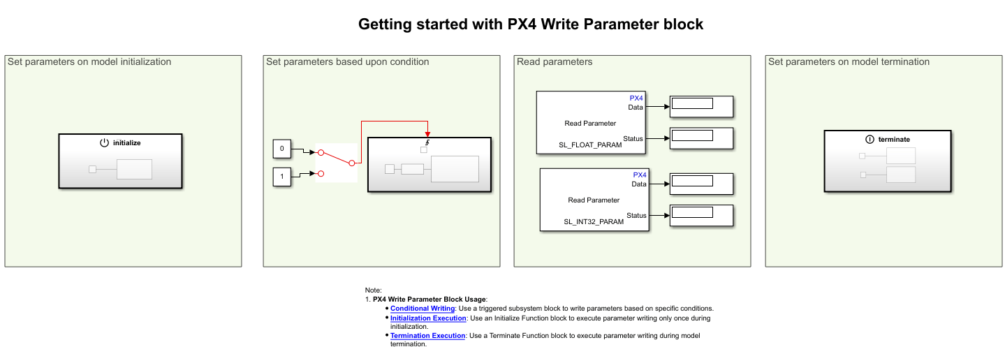
In this example, the PX4 Write Parameter Block is used for:
Conditional Writing: To write parameters based on specific conditions, you can use a Triggered Subsystem block. This block allows you to execute parameter writing only when certain conditions are met.
Inside the Triggered Subsystem, use a PX4 Write Parameter Block to write to
SL_INT32_PARAM.
Initialization Execution: To execute parameter writing only once during initialization, use an Initialize Function block. This block ensures that the parameter writing occurs at the start of the model execution.
Inside this block, use a PX4 Write Parameter Block to set
SL_FLOAT_PARAMto 10.5.
Termination Execution: To execute parameter writing during model termination, use a Terminate Function block. This block allows you to perform cleanup tasks or final parameter writing.
Inside this block, use PX4 Write Parameter Blocks to reset both
SL_FLOAT_PARAMandSL_INT32_PARAMto their desired default values. For example, 0 or another specified reset value.
Note: By default, the parameters, SL_FLOAT_PARAM and SL_INT32_PARAM are added to the PX4 firmware during the hardware setup process. If they are not added, go through the hardware setup process again.
Monitor and Tune the Model
To view the changes done to the parameter in real-time, perform monitor and tune action. Perform these steps to perform signal monitoring and parameter tuning.
1. On the Hardware tab, in the Mode section, select Run on board and then click Monitor & Tune to start signal monitoring and parameter tuning.
Observe real-time parameter changes.
1. On initialization, the SL_FLOAT_PARAM is set to 10.5. Now use the Read Parameter block to continuously monitor the value of SL_FLOAT_PARAM.
2. Toggle the switch from 0 to 1 and observe the increment in SL_INT32_PARAM on each rising edge.
3. When stopping the model, verify that both parameters are reset to their specified values.
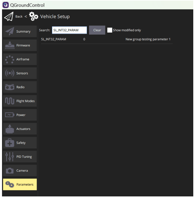
You can also verify the changes using the QGroundControl(QGC).
Navigate to the Parameters section in QGC, and verify
SL_FLOAT_PARAMandSL_INT32_PARAMparameters reflect the expected values during initialization, after switch operations, and after model termination.