Getting Started with Actuator Control over PWM
This example shows you how to use the PX4 Actuator Write block to write actuator values over PWM.
Introduction
UAV Toolbox Support Package for PX4® Autopilots enables you to write actuator values to the Motor ESCs and Servos connected over PWM or UAVCAN/DroneCAN interface.
In this example, you will learn how to create and run a Simulink® model to write actuator values for controlling Motors and Servos.
Prerequisites
If you are new to Simulink, watch the Simulink Quick Start video.
Perform the initial Setup and Configuration of the support package using Hardware Setup screens.
Required Hardware
To run this example, you will need the following hardware:
Supported PX4 Autopilot
Micro USB type-B cable
Cathode Ray Oscilloscope (CRO) or Logic analyzer (for PWM)
Model
Open the px4ActuatorWrite model.
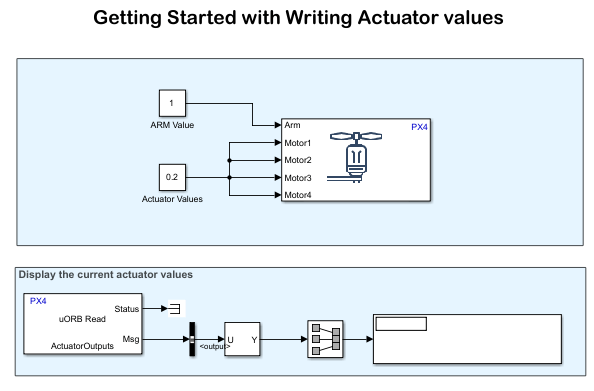
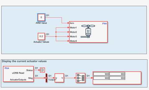
Assuming you are designing a quadcopter and aim to send actuator values to the four motors, this model utilizes the PX4 Actuator Write block to transmit actuator values to the four motors. Passing a true value to the "Arm" input, arms the actuators. In this model, a single value of 0.2 is sent to all four motors to provide 20% thrust.
If your motors are connected and powered, ensure the propellers are removed for safety.
The ActuatorOutputs uORB topic is used to read the actuator values back into Simulink and display them.
Note: ActuatorOutputs will reflect only the values for PWM Main channels. For PWM AUX and UAVCAN, ActuatorOutputs will not show the actuator values that you are writing.
Writing Actuator values over PWM
In this section, you will learn how to configure and write actuator values to the PWM pins.
Step1: Configure Actuators from QGroundControl
For Firmware version 1.14, the actuators must be configured in QGroundControl (QGC) before you can use the PX4 Actuator Write block in Simulink. For more information, see Configure and Assign Actuators in QGC.
1. Connect the PX4 Autopilot to your machine and wait until QGroundControl connects with the hardware.
Note: MAVLink must be enabled over USB (/dev/ttyACM0) for QGC connectivity. For more information, see Enabling MAVLink in PX4 Over USB.
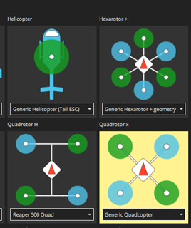
2. For this example, as we are focusing on a quadcopter, select Generic Quadcopter as the airframe in the Vehicle Setup -> Airframe tab of QGC. Reboot the hardware for this change to take effect.
3. After selecting the airframe, go to the Actuator tab (Vehicle Setup -> Actuators) and assign the four motors to the first 4 Main PWM channels, respectively. Based on this selection, the actuator values will now be sent over the PWM Main channels. For example, the values written to Motor1 will be sent to PWM Main Channel 1. Note that the PWM frequency is set to 400Hz.
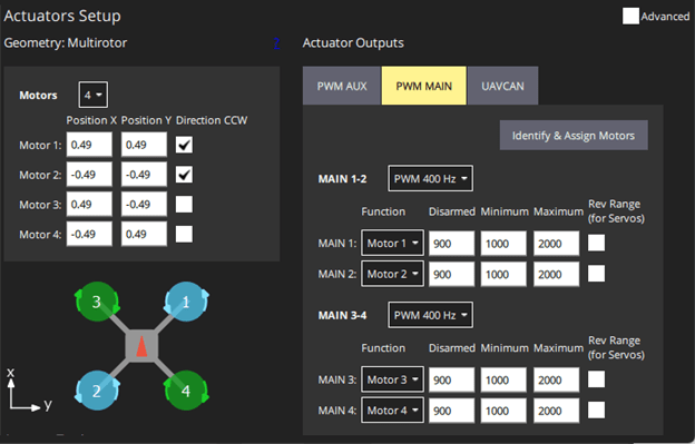
4.Leave the other Main channels and PWM AUX channels as Disabled.
5. You can also adjust the minimum and maximum values based on your requirements and the specifications of your ESC. For example, to maintain consistency with the PX4 PWM Output block, the Disarm, Min, and Max values are updated in this example. However, you can also use the default values.
After completing these selections, close or disconnect QGC.
Note: If you need to use different airframe, motors, or servos, then after selecting the required airframe in QGC, go to the Actuators tab under Vehicle Setup and select the appropriate configuration.
Step2: Configure Model for Supported Pixhawk Hardware
In this section, you will configure the model for the supported Pixhawk hardware.
The model used in this example is configured for Pixhawk 6x hardware. If you are using a different supported Pixhawk hardware, perform these steps.
1. In your Simulink model, Go to Modeling > Model Settings to open the Configuration Parameters dialog box.
2. Click Hardware Implementation pane, and select the required Pixhawk hardware from the Hardware board list.
3. For running in external mode, navigate to Target hardware resources > MAVLink and clear Enable MAVLink on /dev/ttyACM0.
4. Click Apply and OK.
Step3: Configure Model for Supported Pixhawk Hardware
1. Connect one of the first four MAIN PWM channels (for example, Main 1) of the PX4 autopilot to an oscilloscope or a logic analyzer.
2. Run the model using one of the following options.
Monitor & Tune: To run the model for signal monitoring and parameter tuning, on the Hardware tab, in the Mode section, select Run on board and then click Monitor & Tune to start signal monitoring and parameter tuning.

Wait for the code generation to be completed. Whenever the dialog box appears instructing you to reconnect the flight controller to the serial port, click OK and then reconnect the PX4 Autopilot on the host computer.
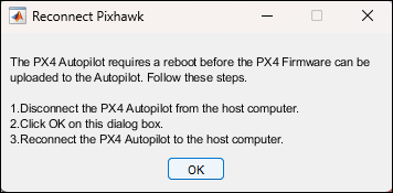
The lower left corner of the model window displays status while Simulink prepares, downloads, and runs the model on the hardware.
Connected IO: To run this model in the Connected I/O mode, on the Hardware tab, in the Mode section, select Connected IO and then click Run with IO.

If the Connected IO firmware is not deployed on the hardware, then the dialog box instructing you to reconnect the flight controller to the serial port appears otherwise the dialog box is not displayed. If the dialog box appears, click OK and then reconnect the PX4 Autopilot on the host computer.
3. Connect the CRO or Logic analyzer to the PWM Main channels 1, 2, 3, and 4.
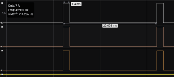
4. Observe the PWM signals and verify the ON time, which should correspond to the values you have input into the block. In this example, an input of 0.2 is provided, and based on the QGC actuator configuration where the Max is 2000 and Min is 1000, you should observe a PWM signal with a width of 1200 microseconds. The frequency is set to |400|Hz, as specified in QGC.
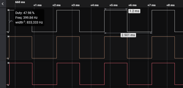
5. The ActuatorOutputs uORB topic will display the PWM values as well. Note that this information will reflect only for Main channels and not for Aux channels.

6.Change the actuator value and observe the PWM signal. The PWM ON value should change according to the actuator value input. Providing a false value to the Arm input will result in the disarm PWM values being displayed.

Writing to Actuator values to Servos
In this example, you learned how to write actuator values to motors using both PWM and UAVCAN interfaces for a Quadcopter airframe. If your airframe also requires servos, you can follow a similar approach.
For example, if you choose a fixed wing airframe, then you need to write actuator values to servo as well along with Motor. You need to configure the servos as well in QGC before writing actuator values from Simulink.
Model
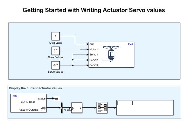
Open the px4ActuatorServoWrite model.
Step1: Configure the Actuators from QGroundControl
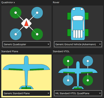
1. Open QGC and after PX4 Autopilot is connected, select Generic Standard Plane as the airframe in the Vehicle Setup -> Airframe tab of QGC. Reboot the hardware for this change to take effect.
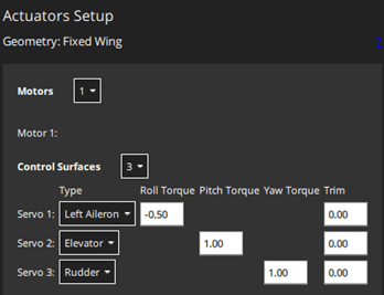
2. After selecting the airframe, go to the Actuator tab (Vehicle Setup -> Actuators). Now, the option to configure servos appears. This example uses three servos.
3. Assign Motor 1 to PWM Main Channel 1, and the servos to the first three Aux channels.
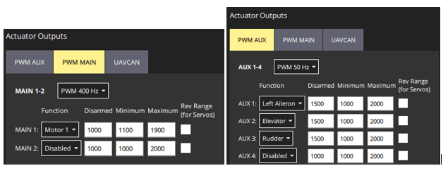
Note: It is recommended to assign Motors to the Main channels and servos to the Aux channels only.
4. Based on the selection you have made, the actuator values written to Servo 1, 2, and 3 will now be sent to Aux channel 1, 2, and 3, respectively. Note that the PWM Main channel frequency is set to |400|Hz, and the Aux channel frequency is set to 50Hz. After completing this setup, close QGC.
Step2: Configure the Model for Servo Write
In this step, modify the example model to direct values to the servos.
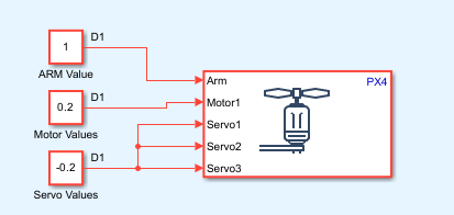
1. Double-click the Actuator Write block in your Simulink model. Select only one Motor in the Motors tab and three servos from the Servos tab.

2. Provide the actuator values to both the motor and servos. For example, assign a value of 0.2 to Motor 1 and -0.2 to all three servos.
Step3: Run the Model and Validate the actuator values
1. Connect the CRO or Logic analyzer to the AUX Channel 1,|2| or 3 and PWM Main channel 1.
2. Run the Simulink model using Monitor and Tune option or in Connected IO mode. Observe the PWM signals in AUX channels.
3. Since the minimum and maximum PWM values are set as 1100 and 1900 respectively in QGroundControl (QGC), a 20% PWM value for motors would be calculated as follows:
|(1900-1100)*0.2+1100 = 1260us|
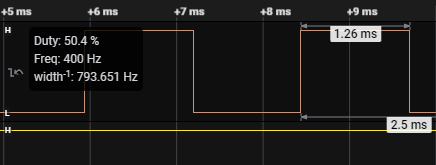
For AUX channels, the Min value is set as 1000 and Max value is 2000. Since for servos the actuator range is [-1, 1], the zero-actuator value will correspond to PWM value 1500. For an actuator value of -0.2, the corresponding PWM value can be calculated using the formula: 1500-0.2*(2000-1000)/2 = 1400. Frequency is |50|hz.
