Closed Loop Control of Buck Converter using Hardware-In-The-Loop (HIL) Simulation
This example uses hardware-in-the-loop (HIL) simulation to implement the closed loop control of buck converter. The control algorithm requires output voltage feedback, which is then fed to the PI controller. The controller outputs the duty ratio which varies to control the output voltage. For more information, see Closed Loop Control of a DC-DC Buck Converter.
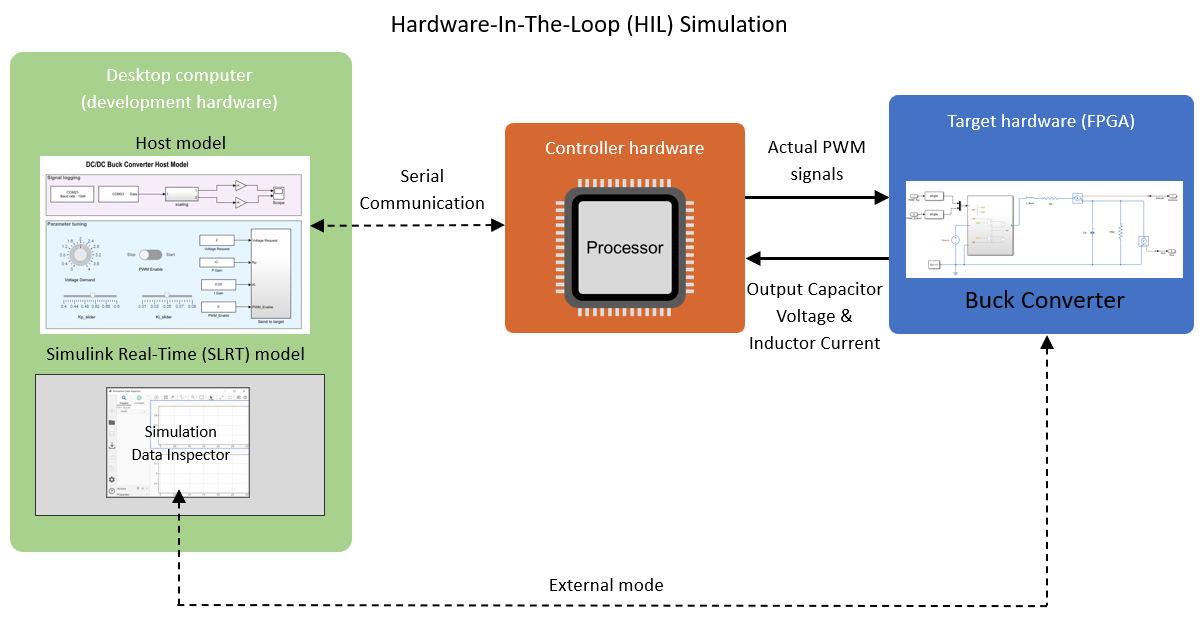
When the actual buck converter is not available, you can use the HIL simulation workflow to validate the control algorithm in real-time by operating a realistic virtual plant. The HIL simulation setup consists of these elements.
Desktop computer or development hardware running Simulink®.
Controller hardware running the code for the controller.
Target hardware (FPGA) running the code for the physical plant.
You must deploy the controller code to the controller hardware and the HDL code for the plant to the FPGA target hardware. Once deployed, the controller executes the control algorithm and generates PWM signals. Simultaneously, the FPGA hardware emulates the buck converter using the HDL code for the plant. This emulation accepts the PWM signals and provides real-time feedback on current and rotor position, replicating the actual plant behavior. The FPGA operates in external mode, logging data in the Simulation Data Inspector of the Simulink Real-Time model.
The Simulink host model running on the desktop computer communicates with the controller using a serial communication protocol. This interaction allows the host model to control the motor operation through communication with the controller.
Open MATLAB Project
The example is packaged as a MATLAB® project. Use one of these methods to open the MATLAB project window:
1. Click Open Project.
2. Run the following command to access the supporting files of the example and open the MATLAB project.
openExample('c2b/ClosedLoopBuckConverterUsingHardwareInLoopHILSimulationExample');
Model
The MATLAB® project has a model folder that includes the following models:
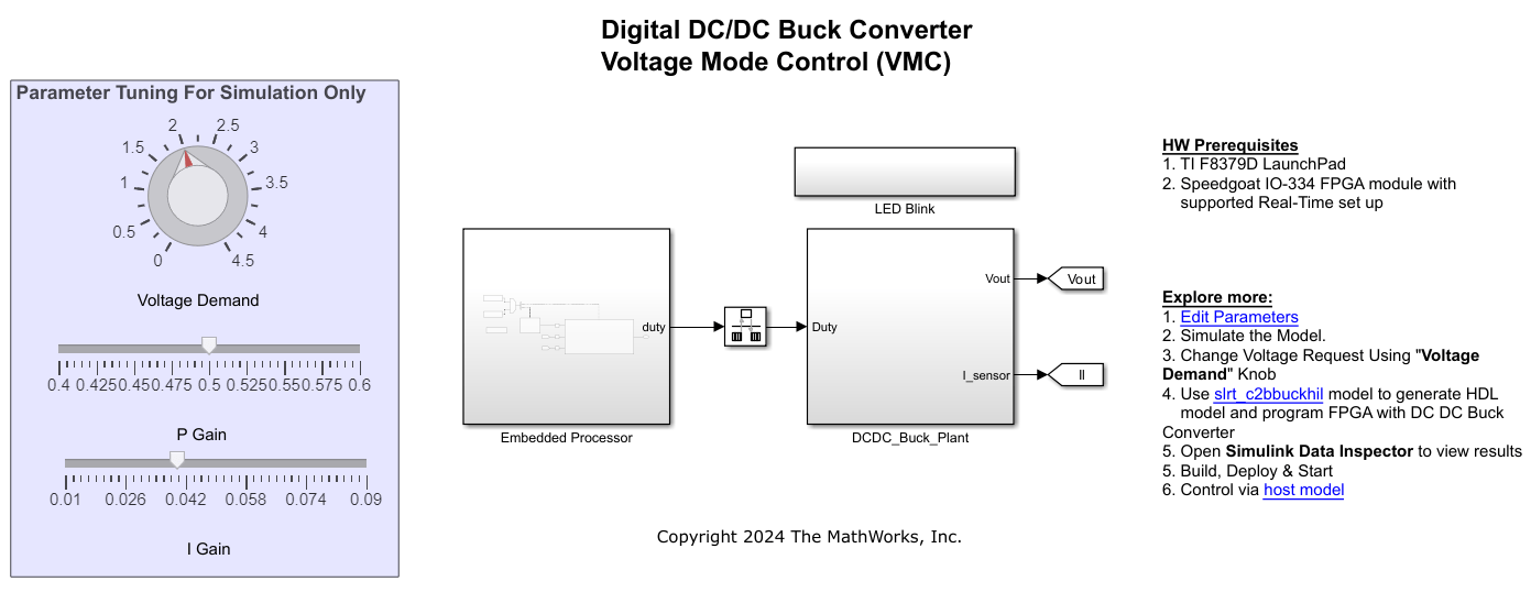
c2bBuckConverterHILModel.slx- This target model contains the control algorithm that you can deploy and run on the controller hardware.
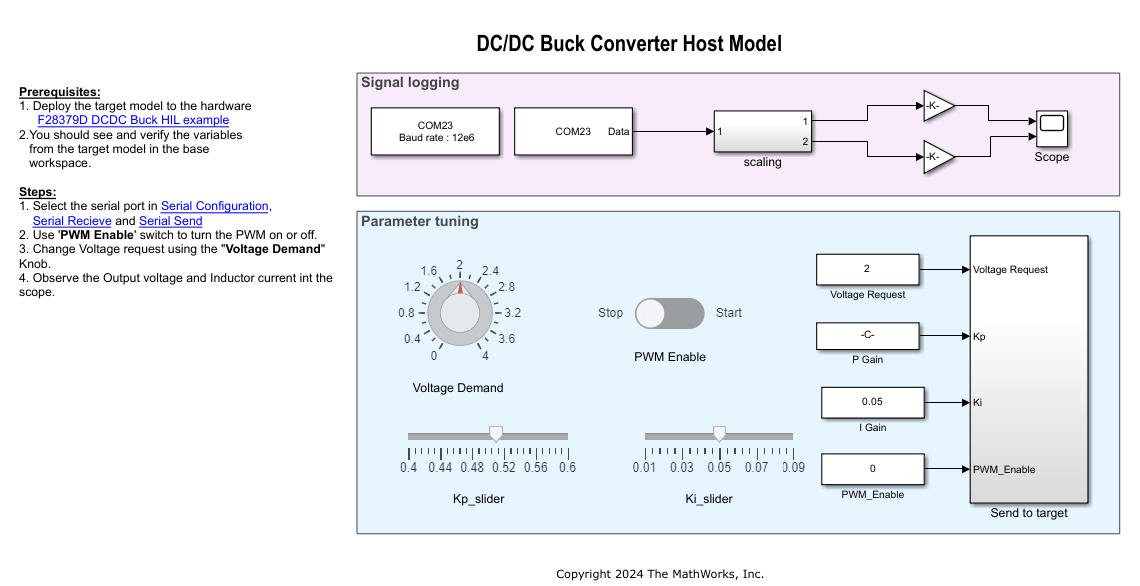
c2bBuckHILHostModel.slx- This is a host model to communicate with the embedded target hardware. Using this model, you can provide various commands to the buck converter such as output voltage reference, PWM enable signal.
Apart from these two models, you will need an FPGA plant model (a buck converter), which you can deploy and run on the FPGA target hardware, and a Simulink® Real-Time™ application model, which you can use to choose the target hardware and deploy the FPGA plant model algorithms. This example uses the plant model gm_c2bbuckhilhdlwrapper_slrt.slx. The plant model captures the PWM duty cycles provided by the controller and, in turn, runs the buck converter to generate and send back the actual ADC voltage and current signals to the controller hardware. You can use this plant model to generate the Simulink Real-Time (SLRT) model and the HDL code for the FPGA target hardware.
Required MathWorks Products
To simulate model:
Simscape™
Simscape™ Electrical™
Fixed-Point Designer™
To generate code and deploy model:
1. C2000™ Microcontroller Blockset
2. Simulink Real-Time™
3. Embedded Coder®
4. HDL Coder™ (required only if you are changing the plant model)
5. Speedgoat I/O Blockset
6. Fixed-Point Designer™
Prerequisites
1. To run the model on Speedgoat, you will require the following 3P tools from Speedgoat website:
Open the Downloads section from the speedgoat website: https://www.speedgoat.com/extranet#/Downloads
Download Speedgoat I/O Blockset for the corresponding MATLAB release you are working on. For. eg: Speedgoat I/O Blockset for R2024a(v9.8.1.1).
Download corresponding HDL Coder integration package for the corresponding speedgoat machine you are working. For eg: IO334-325k(R2024a, v2.0) HDL Coder Integration Package.
2. Update the buck converter parameters in the c2bBuckConverterHILModelData.m parameter script associated with the target models available in the MATLAB project. This script automatically opens when you open the MATLAB project. You can also use the Project window to open this script from the scripts folder.
3. Click Run on the Editor tab to run the parameter script.
Required Hardware
The example supports this hardware configuration: LAUNCHXL-F28379D controller + Speedgoat IO-334 programmable FPGA card.
Prepare Hardware
1. Connect the Speedgoat board to the LAUNCHXL-F28379D controller board as shown in this table.


2. For analog signals, connect the Speedgoat to controller as shown in this table.

For more details on the Speedgoat board, see Speedgoat IO-334 and Speedgoat Connection box.
Simulate Model
Follow these steps to simulate the models included in the project:
1. Open target model c2bBuckConverterHILModel.slx from the model folder included in the MATLAB project.
2. Click Run on the Simulation tab to validate the operation of the buck converter with the Simscape or HDL plant using the radio button on the model. You can increase the simulation speed by reducing the FPGA frequency f_base to 2MHz in c2bBuckConverterHILModelData.m script. Observe the simulation results. Make sure to revert f_base to 200MHz before deploying to FPFA hardware.
3. Open plant model c2bbuckhilhdlwrapper.slx. If you want to change the plant model, update c2bbuckhilhdlwrapper.slx. Simulate c2bBuckConverterHILModel.slx to verify the changes in simulation and proceed with HDL workflow to generate the new SLRT model.
By default, the sample time for the plant model (ts_FPGA_mdl) is set to 500ns.
Note: Adjust the model sample time (ts_FPGA_mdl) if the parameters change.
Generate HDL Implementation Model
1. Open the c2bbuckhil.slx simscape plant model.
2. For HDL code generation compatibility, you run the Simscape HDL Workflow Advisor to generate an HDL implementation model.
To open the Advisor, run the sschdladvisor function for your model:
sschdladvisor('c2bbuckhil.slx')
3. To generate the implementation model, in the Simscape HDL Workflow Advisor, keep the default settings for the tasks, and then run the tasks. Run the tasks in the Advisor by clicking the Run all button. You see a link to the model in the Generate implementation model task. This model has the same name as your original model with the prefix gmStateSpaceHDL_.
Note: The model (c2bbuckhil.slx) already uses dynamic switches obtained by replacing the regular IGBTs. For more information, see sschdl.generateOptimizedModel.
Prepare Implementation Model for HDL Code Generation
1. In the project, you can find the generated model named c2bbuckhilhdlwrapper, which has been modified to run on Speedgoat IO334. This model is located in the component folder of the Simulink project. For more information, see Deploy Simscape Buck Converter Model to Speedgoat IO Module Using HDL Workflow Script.
The model contains a switched linear Simulink replacement of the original buck converter model. The implementation model replaces the Simscape subsystem with the HDL-compatible algorithm that performs the state-space computations.
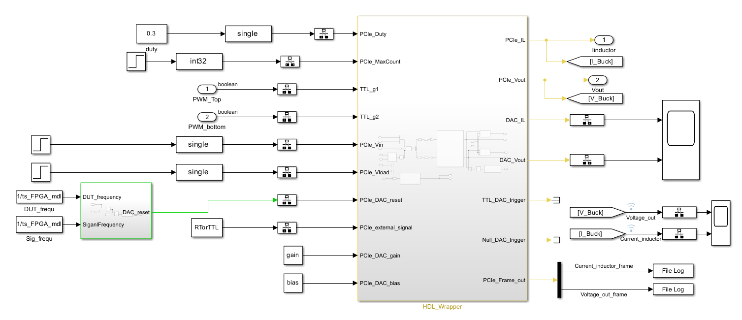
Prepare Simulink Real-Time Interface Model for Real-Time Simulation
Run the HDL Workflow Advisor for the implementation model. To open the HDL Workflow Advisor, use the hdladvisor function. For example:
hdladvisor('c2bbuckhilhdlwrapper/HDL_Wrapper')
To learn about the tasks in the Advisor, right-click that task, and select What's This?. See Getting Started with the HDL Workflow Advisor.
Running the HDL Advisor generates RTL code and IP core, creates a Vivado project, builds the FPGA bitstream, and then generates the Simulink Real-Time Interface model. Ensure to change the sample time for the blocks outside the subsystem running in FPGA to Tcpu which is set to 50 microsecond in the script.
Generate Code and Deploy Model to Target Hardware
1. Complete the hardware connections.
2. Generate the code for c2bBuckConverterHILModel.slx model and deploy it on the TI F28379d Launchpad by clicking on the Build, deploy and start from the Simulink toolstrip.
Note: To ensure that CPU2 is not configured to use the board peripherals intended for CPU1, load a sample program to the CPU2 of the LAUNCHXL-F28379D. For example, you can load the program that operates the CPU2 blue LED by using GPIO31 (c28379D_cpu2_blink.slx). For more information about the sample program or model, see the Task 2 - Create, Configure and Run the Model for TI Delfino F28379D LaunchPad (Dual Core) section in Getting Started with Texas Instruments C2000 Microcontroller Blockset.
3. Open the plant model gm_c2bbuckhilhdlwrapper_slrt.slx and build the model. Program the FPGA using this model and run it for 500 seconds by executing below lines in MATLAB command window.
tg = slrealtime; connect(tg); mdl = 'gm_c2bbuckhilhdlwrapper_slrt'; open_system(mdl); modelSTF = getSTFName(tg); set_param(mdl,"SystemTargetFile",modelSTF) evalc('slbuild(mdl)'); load(tg,mdl); tg.setStopTime(500); start(tg);
NOTE:
If you want to update the plant model, update
c2bbuckhilhdlwrapper.slxand follow HDL workflow to generate the SLRT modelgm_c2bbuckhilhdlwrapper_slrt.slxand program the FPGA.The voltage and current signals are captured at the rate of 1us. (frame = 500ns/1us)
4. Click the host model hyperlink in c2bBuckConverterHILModel.slx target model to open the host model. You can also use the MATLAB project window to open the host model c2bBuckHILHostModel.slx.
5. Turn the Stop-Start slider switch available in the Simulation Dashboard area to Enable PWM for the buck converter.
6. In the host model, open the blocks Host Serial Setup, Host Serial Receive, and Host Serial Transmit, and select a Port.
7. Click Run on the Simulation tab to run the host model.
8. Review the logged signals in the scope.
Results
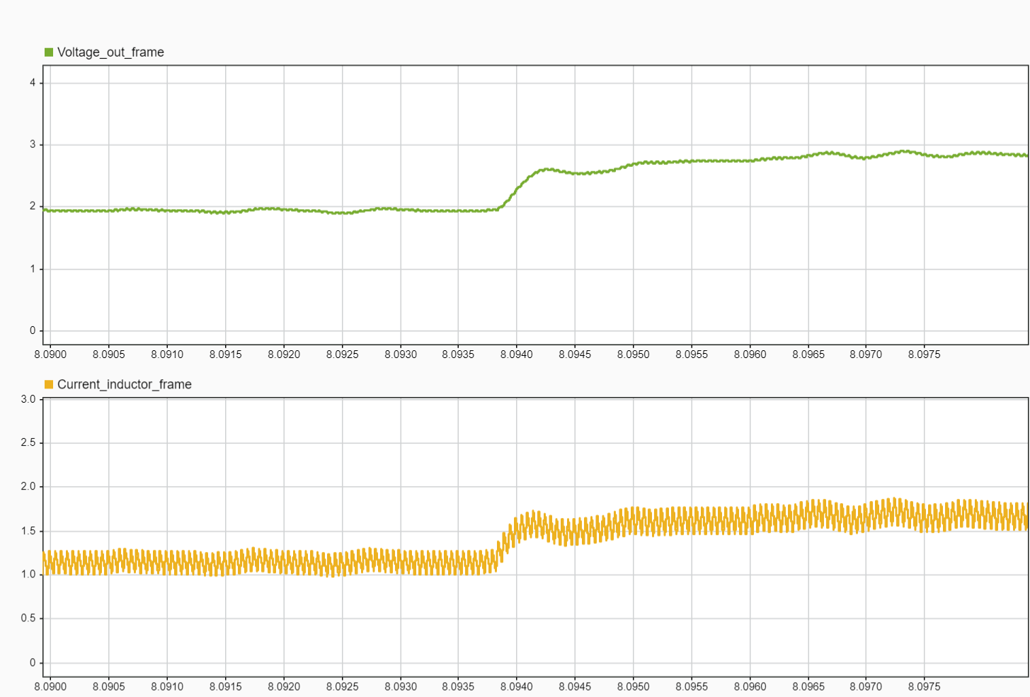
Controller side: Signals feedback from TI F28379D LaunchPad shows ADC feedback signals. Observing on the LaunchPad, the output voltage changes from 2V to 3V.
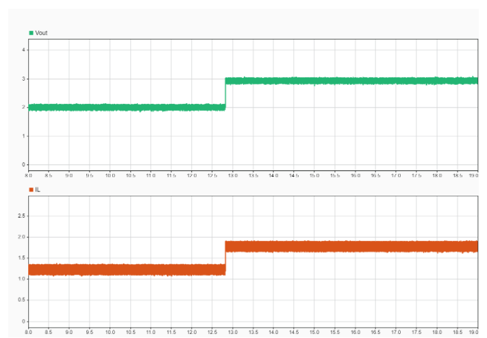
The HIL results from the Speedgoat are obtained when running the gm_c2bbuckhilhdlwrapper_slrt.slx model in external mode with the host computer. The signals are logged in SDI at a 1 microsecond interval.
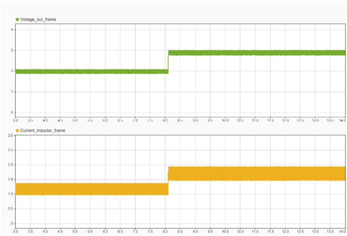
Observe the zoomed-in version of the above results for a detailed view.
