Develop and Verify a Quadcopter System Architecture
R2026bThis example shows an end-to-end workflow for verifying a simple quadcopter design using a model-based systems engineering (MBSE) approach, incorporating requirements engineering, system architecture, design implementation, and requirements verification. In this example, you will learn how to define requirements, create a system architecture, implement the design, and verify that the quadcopter follows a predefined set of waypoints.
To open the project, enter this command.
openProject("VerificationBasedMBSE");Specify Requirements for Quadcopter Design and Trajectory
Use Requirements Toolbox™ to author requirements in the Requirements Editor (Requirements Toolbox). If necessary, you can also import requirements from a Word (.docx), Excel® (.xlsx), or ReqIF file to Requirements Toolbox. For more information, see Import Requirements from Third-Party Applications (Requirements Toolbox).
The
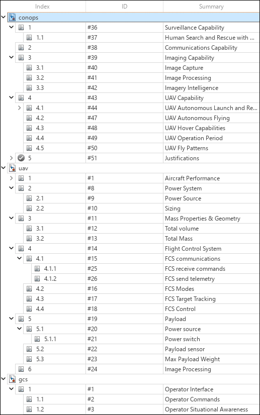
conops.slreqxrequirement set contains high-level requirements, includingSurveillance Capability,Communications Capability,Imaging Capability, andUAV Capability.The
uav.slreqxrequirement set contains detailed requirements for the quadcopter, includingAircraft Performance,Power System,Mass Properties & Geometry,Flight Control System,Payload, andImage Processing.The
gcs.slreqxrequirement set contains details ofOperator Interface.
Requirements are organized into parent and child requirements to facilitate verification testing and maintain end-to-end traceability through a digital thread.
Create Digital Thread Using Data Traceability
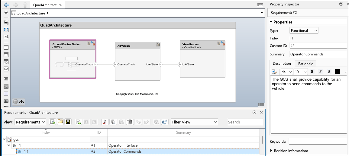
You can use the Requirements Manager (Requirements Toolbox) to view the bidirectional traceability between the architecture, behavior models, and test cases and the project requirements. You can also link requirements to associated components to maintain traceability. To open the Requirements Manager, in the lower-right corner of the canvas, in the Requirements toolbar, select Enter perspective. From there, you can view the details of the requirements file used in the model. You can also drag requirements onto components in the architecture model canvas to establish links. Once linked, a rectangular box displays on the top right corner of the component header.
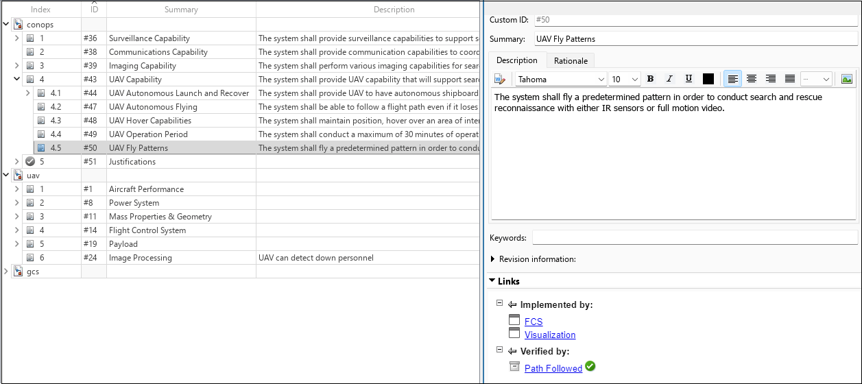
You can also link requirements to test cases. The Requirements Editor (Requirements Toolbox) displays the requirements and the test cases to which they are linked. To view this information, right-click any requirement in the Requirements Manager and select Show in Requirements Editor.
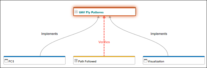
You can also use a traceability diagram to trace requirements back and check that tests verify the requirements. From the Requirements Editor, navigate to Analysis > Traceability Diagram.
Author System Architecture of Quadcopter Design
You can use System Composer™ to develop a system architecture from the project requirements and maintain traceability throughout the design process. This section describes the quadcopter architecture from multiple perspectives, including system behavior using activity diagrams, structural decomposition of architecture components, implementation of component behaviors, and visualization of vehicle operation during simulation. These models provide a comprehensive view of the quadcopter system and its interactions.
Describe System Behavior Using Activity Diagrams
You can use an activity diagram to describe the flow of data through actions to validate functional system design. For more information, see Describe System Behavior Using Activity Diagrams. To open the activity diagram, use this command.
open("QuadSearchandRescue.slx");
The activity diagram shows the overall flow of the system architecture of quadcopter following the waypoints. The token represents the sequential phases which are accomplished by the quadcopter as it advances.
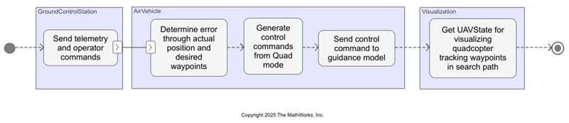
The activity diagram is a functional flow representation of the events that occur in the quadcopter architecture model.
Describe Structure of Quadcopter Architecture Model
To open the QuadArchitecture.slx architecture model, on the Project tab, under Shortcuts, select QuadSystemArchitecture.
The architecture includes components, ports, and connectors that provide a clear representation of the relationships between interfaces and components. The quadcopter system architecture has three main components and their respective subsystems.
The
GroundControlStationcomponent is responsible for sending custom operator commands to the vehicle in operation.The
AirVehiclecomponent represents the quadcopter model and receives operator commands or instructions from the Ground Control Station (GCS). This component transmits the UAV state and telemetry that enable the quadcopter to track the predefined waypoints.The
Visualizationcomponent helps visualize the quadcopter behavior that tracks the waypoints to show the results of the simulation.
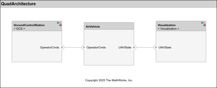
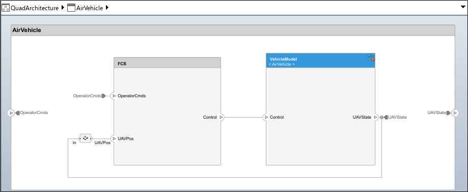
The AirVehicle component consists of two subcomponents, FCS and VehicleModel, that process the operator commands as input to provide the UAV state as output.
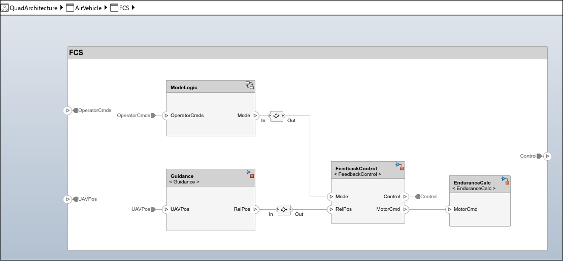
The Flight Control Station (FCS) component, which processes operator commands, consists of four subcomponents: ModeLogic, Guidance, FeedbackControl, and EnduranceCalc.
The
ModeLogiccomponent determines and implements the quadcopter mode based on the operator command.The
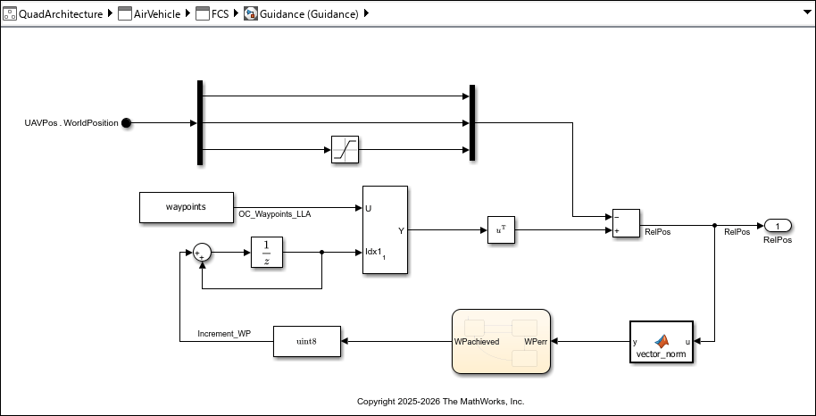
Guidancecomponent determines the relative position from the waypoints and the UAV state.The
FeedbackControlcomponent outputs the control command to the vehicle model or quadcopter for processing.The
EnduranceCalccomponent calculates flight endurance, which is how long the quadcopter can fly continuously without landing. Flight endurance is described by this equation:
*60
The VehicleModel component receives control commands and provides the UAV state for visualization.
To extend elements with metadata for the architecture models, use the stereotypes applied to the components to record property values. For more information, see Define and Style Stereotypes in Profiles.
Design Quadcopter Components and Model Behaviors
To design the quadcopter components and model behavior, Simulink®, Stateflow®, and UAV Toolbox™ licenses are required. Each subcomponent of the quadcopter is linked to a Simulink model, which describes system behavior.
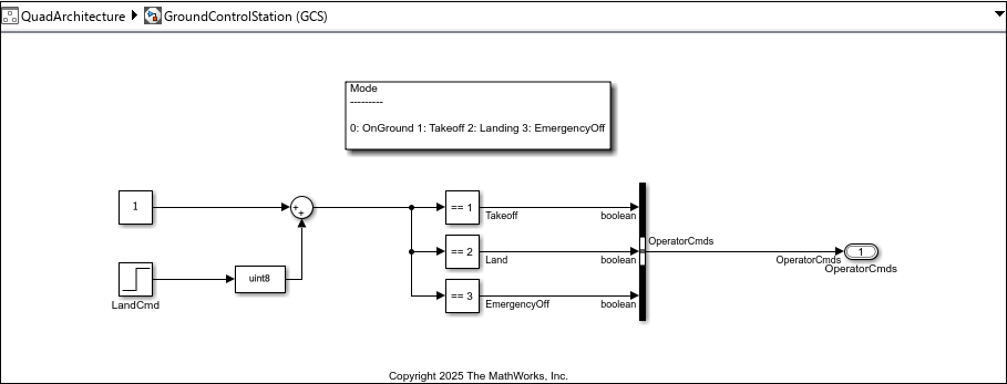
The GroundControlStation component represents the ground control station (GCS).
The GCS sends the operator commands
OperatorCmdsto control the quadcopter and receives telemetry data reporting its status and performance.Quadcopter mission modes are set as
OnGround = 0,Takeoff = 1,Landing = 2, andEmergencyOff = 3.Landing command to the quadcopter is fed as an input to the GCS.
The
QuadData.slddfile is used to manage and store data for the models. For more information, see Architectural Data Editor.
The AirVehicle component represents the quadcopter model. This component comprises FCS and Vehicle Model subcomponents. The Mode logic, Guidance, and Feedback Control components form an integral part of FCS.
Mode logicimplements the quadcopter mode based on the operator command. The operator command providesMissionMode, whose default value is1(flying) to determine the mode of the quadcopter.The
Guidancemodel represents the guidance system. Predefined waypoints are fed as a reference. The relative position error is calculated from the difference between the waypoints and the observed position of the quadcopter.
The
FeedbackControlmodel represents the feedback control system, which provides the control commands to the vehicle model. The quadcopter mode is the control input that determines the port to be selected as output. The model uses the variablesRoll,Pitch,YawRate, andThrust.
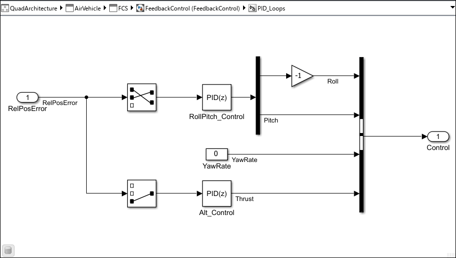
The FeedbackControl model uses a proportional-integral-derivative (PID) controller for attitude and thrust control. PID provides greater waypoint tracking accuracy than the simpler proportional-derivative (PD) design. The integral term eliminates steady-state error during hover dwells and reduces position drift during trajectory tracking, resulting in tighter adherence to commanded waypoints across all trajectory types.
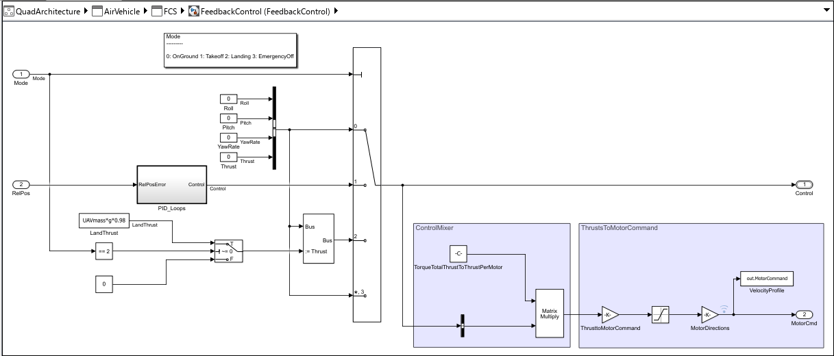
The control input variables Roll, Pitch, YawRate, and Thrust are assumed to be zero when quadcopter is at OnGround or in EmergencyOff mode. The relative position error is fed as an input to the PID controller, PID_Loops. When the quadcopter is in Takeoff mode (flying), the PID controller regulates the control input variables Roll, Pitch, YawRate, and Thrust. During this process, YawRate is maintained at zero to create stable heading and to accurately track waypoints.
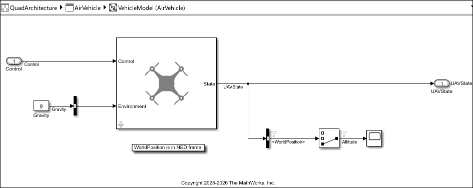
The VehicleModel component implements the quadcopter. A simple guidance model from UAV Toolbox is used to model the dynamics of the quadcopter. The guidance model calculates the UAV state from the control command. Altitude is negative, as the WorldPosition is considered in NED frame. The starting point of the quadcopter is set to [0,0,-0.15]. Simulation stops once the quadcopter lands after tracking the waypoints.
Implement Visualization Quadcopter Path Using UAV Animation Block
The Visualization component visualizes the quadcopter following predefined waypoints by receiving the UAVState data and animating the quadcopter. For more information, see UAV Animation (UAV Toolbox).
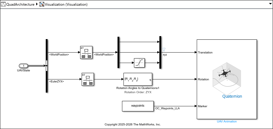
Set these UAV Animation block parameters:
Number of UAVs:
1UAV Type:
MultirotorUAV size:
1UAV mesh color:
[1 0 0]UAV mesh and trajectory alpha:
1Select Always open output figure at start of simulation
Plot axis limits:
[-Inf Inf;-Inf Inf;-Inf Inf]Max number of samples per trajectory: 100000
Inertial frame in z-axis direction:
DownRotation format:
QuaternionSample time:
-1
Simulate Quadcopter and View Design Implementation Results
To simulate the flight path of the quadcopter, click Run.
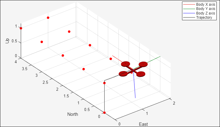
The quadcopter finally lands on ground level.
Select from Three Quadcopter Trajectories
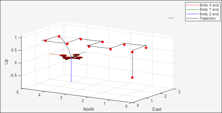
This example provides three preconfigured trajectory types to visualize waypoint tracking and quadcopter behavior.
Square: Ten waypoints at fixed altitude that form a square pattern. Square waypoint tracking tests sharp turns and hover-dwell behavior. This trajectory is the default.
Spiral: Descending helix. Tests continuous descent tracking. Use this trajectory for proof of concept.
Circular: Derived from Aerospace Blockset™ live task. Tests smooth sustained tracking.
For more information on different trajectories, see Model a Quadcopter Based on Parrot Minidrones (Aerospace Blockset).
Select a trajectory by editing the true and false flags in this code block.
%% Select Trajectory
% Set to true to switch between waypoint configurations
isSquare = true; % default
isSpiral = false;
isCircular = false;
open_system('QuadArchitecture');
load_system('FeedbackControl');
[wp, landTime] = configureTrajectory(isSquare, isSpiral, isCircular);

% Write to dictionary
padded = [wp; zeros(90, 3)];
ddObj = Simulink.data.dictionary.open('QuadData.sldd');
dDataSectObj = getSection(ddObj, 'Design Data');
entry = getEntry(dDataSectObj, 'waypoints');
setValue(entry, padded);
entry_lt = getEntry(dDataSectObj, 'landTime');
setValue(entry_lt, landTime);
saveChanges(ddObj);

% Simulate
sim('QuadArchitecture');
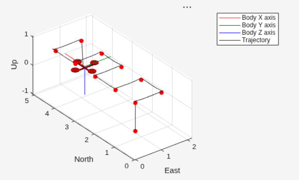
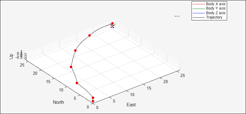
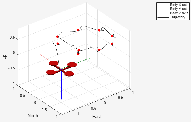
Endurance Observation
After the quadcopter lands and the simulation results are recorded, you review the endurance results:
The Display block shows flight endurance in minutes for the current trajectory mode configuration. This value represents how long the quadcopter can fly continuously in one flight without refueling or landing.
The conceptual formula is endurance (hr) = battery capacity (Ah) / power consumption (W). The implementation calculates endurance in minutes with specific assumptions about hover thrust, propeller diameter, and overall efficiency.
The endurance value is based on fixed component parameters (battery capacity, mass, propeller size) and does not change when switching trajectory types.
In iterative design practice, if endurance is insufficient, engineers would modify component parameters (larger battery, lighter frame, more efficient propellers) and resimulate to observe the impact.
For a dedicated static roll-up approach to this endurance calculation, see Calculate Endurance Using Quadcopter Architectural Design.
Verify Quadcopter Flight System
You can use Simulink Test™ to test and verify the requirements for a low-fidelity system, such as this quadcopter. For more information, see Verify Requirements by Using Tests (Requirements Toolbox).
To inspect or modify the tests, load the test and open Simulink Test Manager using these commands.
sltest.testmanager.load('QuadcopterTests.mldatx');
sltest.testmanager.view
Simulink Test Manager runs a preconfigured test found in QuadcopterTests that performs three checks:
Waypoint tracking accuracy — All waypoints reached within tolerance and in order
Hover capability — Initial hover altitude hold, dwell hover settle at waypoints, end hover position hold before landing
Altitude hold — Altitude stays in band during tracking (constant for square or circular, and monotonically descending for spiral)
To check whether the quadcopter tests pass and to verify the requirements, on the toolstrip for the QuadArchitecture model, on the Simulation tab, click Run.
Tolerances automatically adjust per trajectory type:
Square: tightest (sharp waypoints are welldefined reference points)
Circular: loosest (smooth continuous path allows more variation)
Spiral: intermediate
For advanced validation concepts, see Validating Quadcopter Requirements and System Architecture with Simulation.
Interpreting Results
If the results pass across all trajectories, then the system meets verification criteria for all supported flight scenarios.
If a check fails, then investigate controller parameter settings. Consider whether the issue is architectural (component design) or controller-related (tuning).
If you have a Simulink Test license, you can edit and modify the tests and parameters for other use cases.
Summary
The quadcopter system architecture example uses System Composer to show a model-based systems engineering workflow.
Decompose the quadcopter into key components, define their ports and interfaces, and build a hierarchical model.
Link requirements directly to architectural elements with Requirements Toolbox to maintain traceability and consistency throughout the design.
Explore different flight scenarios using multiple trajectory types and a dynamic endurance calculation from architecture properties.
You link Simulink behaviors to System Composer components to connect high-level architecture with detailed simulation models. By simulating and testing the integrated model, you confirm that system behavior meets requirements. The tools in this example allow you to collaborate, track changes, and iterate efficiently, making this workflow ideal for complex, multidisciplinary projects. Linking requirements and verifying design early helps you reduce integration risks and improve overall design quality. Simulation and verification with three automated checks across all trajectories informs design decisions.
Supporting Functions
The configureTrajectory function adjusts the PID controller to set three different kinds of waypoint tracking systems for the quadcopter flight path.
function [wp, landTime] = configureTrajectory(isSquare, isSpiral, isCircular)
if isSquare % Set square waypoints
        wp = [0 0 -1;0 1 -1;1 1 -1;1 0 -1;2 0 -1;2 1 -1;3 1 -1;3 0 -1;4 0 -1;4 1 -1];
        % PID gains  for Altitude
        set_param('FeedbackControl/PID_Loops/Alt_Control', 'P', '-0.45');
        set_param('FeedbackControl/PID_Loops/Alt_Control', 'I', '-0.044');
        set_param('FeedbackControl/PID_Loops/Alt_Control', 'D', '-0.253');
        set_param('FeedbackControl/PID_Loops/Alt_Control', 'N', '100');
        set_param('FeedbackControl/PID_Loops/Alt_Control', 'FilterMethod', 'Forward Euler');
        set_param('FeedbackControl/PID_Loops/Alt_Control', 'LimitOutput', 'off');

        % PID gains for Roll & Pitch
        set_param('FeedbackControl/PID_Loops/RollPitch_Control', 'P', '-0.006');
        set_param('FeedbackControl/PID_Loops/RollPitch_Control', 'I', '-0.0001');
        set_param('FeedbackControl/PID_Loops/RollPitch_Control', 'D', '-0.15');
        set_param('FeedbackControl/PID_Loops/RollPitch_Control', 'N', '100');
        set_param('FeedbackControl/PID_Loops/RollPitch_Control', 'FilterMethod', 'Forward Euler');
        set_param('FeedbackControl/PID_Loops/RollPitch_Control', 'LimitOutput', 'off');
        % LandTime
        landTime = 24;

        % Set spiral waypoints
elseif isSpiral
        wp = [1.0000 0.0200 -0.1000;0.8000 0.6000 -0.2000;0.2900 0.9600 -0.3000;-0.3300 0.9500 -0.4000;-0.8200 0.5700 -0.5000;-1.0000 -0.0200 -0.6000;-0.8000 -0.6000 -0.7000;-0.2900 -0.9600 -0.8000;0 0 0;0 0 0];
        wp = wp(~all(wp == 0, 2), :);  % remove zero rows

        % PID gains for altitude control
        set_param('FeedbackControl/PID_Loops/Alt_Control', 'P', '-1.2');
        set_param('FeedbackControl/PID_Loops/Alt_Control', 'I', '-0.044');
        set_param('FeedbackControl/PID_Loops/Alt_Control', 'D', '-0.253');
        set_param('FeedbackControl/PID_Loops/Alt_Control', 'N', '100');
        set_param('FeedbackControl/PID_Loops/Alt_Control', 'FilterMethod', 'Forward Euler');
        set_param('FeedbackControl/PID_Loops/Alt_Control', 'LimitOutput', 'off');

        % PID gains for lateral control
        set_param('FeedbackControl/PID_Loops/RollPitch_Control', 'P', '-0.06');
        set_param('FeedbackControl/PID_Loops/RollPitch_Control', 'I', '-0.0001');
        set_param('FeedbackControl/PID_Loops/RollPitch_Control', 'D', '-0.15');
        set_param('FeedbackControl/PID_Loops/RollPitch_Control', 'N', '100');
        set_param('FeedbackControl/PID_Loops/RollPitch_Control', 'FilterMethod', 'Forward Euler');
        set_param('FeedbackControl/PID_Loops/RollPitch_Control', 'LimitOutput', 'off');
        % LandTime
        landTime = 26;

    else isCircular
        % circular waypoints
        wp = [0 0 -1;7.7254   1.2236 -1;14.6946  4.7746 -1;20.2254  10.3054 -1;23.7764  17.2746 -1;25.0000  25.0000 -1;0  0 0;0  0 0;0  0 0;0  0 0];
        wp = wp(~all(wp == 0, 2), :);  % remove zero rows

        % PID gains for altitude control
        set_param('FeedbackControl/PID_Loops/Alt_Control', 'P', '-1.2');
        set_param('FeedbackControl/PID_Loops/Alt_Control', 'I', '-0.044');
        set_param('FeedbackControl/PID_Loops/Alt_Control', 'D', '-0.253');
        set_param('FeedbackControl/PID_Loops/Alt_Control', 'N', '100');
        set_param('FeedbackControl/PID_Loops/Alt_Control', 'FilterMethod', 'Trapezoidal');
        set_param('FeedbackControl/PID_Loops/Alt_Control', 'LimitOutput', 'on');
        set_param('FeedbackControl/PID_Loops/Alt_Control', 'UpperSaturationLimit', '3.0');
        set_param('FeedbackControl/PID_Loops/Alt_Control', 'LowerSaturationLimit', '-0.5');
        set_param('FeedbackControl/PID_Loops/Alt_Control', 'AntiWindupMode', 'clamping');

        % PID gains for lateral control
        set_param('FeedbackControl/PID_Loops/RollPitch_Control', 'P', '-0.08');
        set_param('FeedbackControl/PID_Loops/RollPitch_Control', 'I', '-0.0001');
        set_param('FeedbackControl/PID_Loops/RollPitch_Control', 'D', '-0.15');
        set_param('FeedbackControl/PID_Loops/RollPitch_Control', 'N', '50');
        set_param('FeedbackControl/PID_Loops/RollPitch_Control', 'FilterMethod', 'Trapezoidal');
        set_param('FeedbackControl/PID_Loops/RollPitch_Control', 'LimitOutput', 'on');
        set_param('FeedbackControl/PID_Loops/RollPitch_Control', 'UpperSaturationLimit', '0.7');
        set_param('FeedbackControl/PID_Loops/RollPitch_Control', 'LowerSaturationLimit', '-0.7');
        set_param('FeedbackControl/PID_Loops/RollPitch_Control', 'AntiWindupMode', 'clamping');

        % LandTime
        landTime = 30;
end
end
See Also
Blocks
- UAV Animation (UAV Toolbox)
Apps
- Requirements Editor (Requirements Toolbox) | Requirements Manager (Requirements Toolbox) | Architectural Data Editor

