Reading Accelerometer Values from an I2C based Sensor Connected to a PX4 Autopilot
This example shows how to use UAV Toolbox Support Package for PX4 Autopilot to configure and read accelerometer values from an I2C based sensor.
Introduction
UAV Toolbox Support Package for PX4 Autopilot enables you to use the I2C interface to communicate with I2C based devices connected to the PX4 Autopilots. In this example, you will learn how to communicate with sensor MPU9250. The MPU9250 is a 9 degree of freedom (DOF) inertial measurement unit (IMU) used to read acceleration, angular velocity, and magnetic field in all three dimensions. This sensor is interfaced with the PX4 Autopilot using the I2C bus. For more information on the device, refer to the MPU9250 datasheet.
This example shows how to program the PX4 Autopilot to read the accelerometer values from the sensor using the I2C bus. It also illustrates how to program the PX4 Autopilot to initialize the sensor with some configuration settings.
Prerequisites
If you are new to Simulink, watch the Simulink Quick Start video.
Required Hardware
To run this example, you will need the following hardware:
Supported PX4 Autopilot
USB cable
Pixhawk connectors
Model
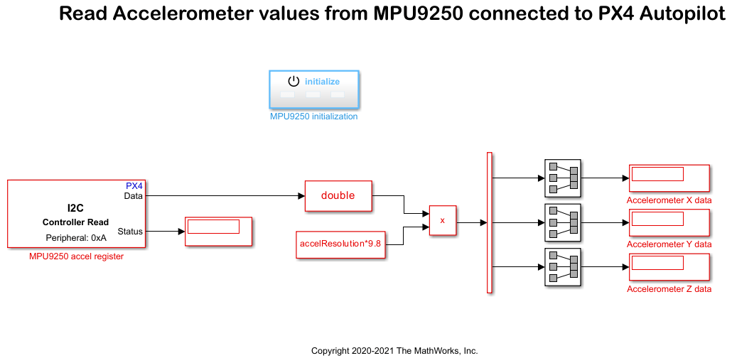
Open the px4demo_I2C_MPU9250 model.
Step 1 - Connect the MPU9250 Sensor to the Pixhawk Hardware
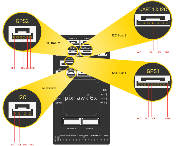
In this section, connect the MPU9250 sensor to the Pixhwak board. Decide the bus you want to connect to the I2C device. Refer to the I2C Bus Port Numbers for Labels on PX4 Autopilots for finding buses and pinout for your board. For example, consider Pixhawk 6x as the hardware board, then the bus mapping will be similar to the following image. It is recommended to connect the I2C device to the I2C specific port, that is I2C. In this example, corresponding I2C bus number is 3. If you are using a different board, see I2C Bus Port Numbers for Labels on PX4 Autopilots for buses and pinouts. Connect the sensor to corresponding pin of the I2C port. You might require a corresponding Pixhawk connector for that port. Refer to the following image for pinouts.
Step 2 - Configure the Model for Supported Pixhawk Hardware
In this section, you will configure the model for the supported Pixhawk hardware.
1. Open the px4demo_I2C_MPU9250 model. The model is configured for Pixhawk 6x. If you have a different supported Pixhawk hardware follow the remaining steps to select the required hardware.
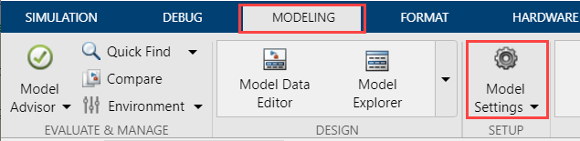
2. In your Simulink model, Open the Modeling tab and press CTRL+E to open Configuration Parameters dialog box.
3. Select the Hardware Implementation pane and select your required Pixhawk hardware from the Hardware board parameter list. Do not change any other settings.
4. Click OK.
Step 3 - Configure the Model to Read Accelerometer Values Using the I2C Read Block
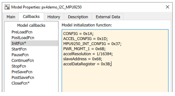
The configuration values and registers used in this example are defined in InitFcn callback present in the Model Properties of the example model. These values are chosen by referring to the MPU9250 datasheet.
1. Configure I2C Read block.
Open the I2C Read block. Notice that the Peripheral register address parameter of the block is set to
accelDataRegister. This corresponds to a 7-bit address of 1101000 (0x68 in hexadecimal) according to the MPU9250 datasheet.
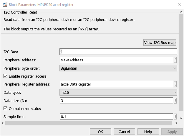
Accel values along x, y, and z are stored in 3 consecutive 16 bit registers starting from 0x3B. Enter the Peripheral register address as
accelDataRegister(0x3B). Select the Data type asint16, Peripheral byte order asBigEndian, set Data size (N) to3, and Sample Time to0.1. This initiates an I2C read request every 0.1 second.
Click OK.
2. Sensor Initialization
The Initialization block is used for initializing sensor configuration registers. This is a onetime operation, and initialization block can be used to do such one-time configurations.
In the MPU9250 initialization block there are three different subsystems power register configuration, Sensor device configuration, accelerometer register configuration.
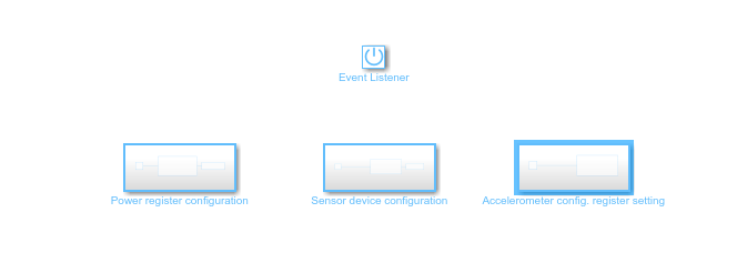
In Power register configuration, PWR_MGMT_1 register of MPU9250 is configured using I2C Controller Write block.
In Sensor device configuration, MPU9250_INT_CONFIG register of MPU9250 is configured using I2C Controller Write block.
In Accelerometer register configuration, ACCEL_CONFIG register of MPU9250 is configured using I2C Controller Write block.
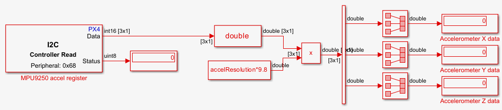
3. Notice the following points in the model:
The Data Type Conversion block is used to convert the read data to double for multiplying with the accelerometer resolution(
accelResolution).
The
accelresolutionis chosen assuming the accelerometer range is 2g and is, multiplied using a product block.
The Demultiplexer block used to extract acceleration along 3 different axes into three different signals from a 3X1 vector.
Step 4 - Configure and Run the Model
In this section, you will monitor the accelerometer values by signal monitoring and parameter tuning. You can also run the model using the Connected IO option.
1. In the Simulation tab, specify the stop time for parameter tuning simulation. The default value for the Stop time parameter is 10.0 seconds. To run the model for an indefinite period, enter inf.
2. Run the model using one of the following options.
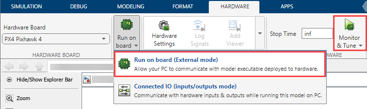
Monitor & Tune: To run the model for signal monitoring and parameter tuning, on the Hardware tab, in the Mode section, select Run on board and then click Monitor & Tune to start signal monitoring and parameter tuning.
Wait for the code generation to be completed. When the dialog box appears instructing you to reconnect the flight controller to the serial port, click OK and then reconnect the PX4 Autopilot on the host computer.

The lower left corner of the model window displays status while Simulink prepares, downloads, and runs the model on the hardware.
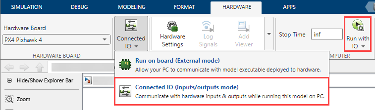
Connected IO: To run this model in the Connected I/O mode, on the Hardware tab, in the Mode section, select Connected IO and then click Run with IO.
If the Connected IO firmware is not deployed on the hardware, then the dialog box instructing you to reconnect the flight controller to the serial port appears otherwise the dialog box is not displayed. If the dialog box appears, click OK and then reconnect the PX4 Autopilot on the host computer.
3. Notice that the Display blocks Accelerometer X data, Accelerometer Y data, Accelerometer Z data, in the model shows the accelerometer reading in m/s^2 along x, y, and z direction respectively.
Note: If you are not able to read data, the display block connected to the Status port can be used to understand the read status.
0 - indicates a success
1 - indicates a failure in opening the bus.
2 - indicates a failure in read operation, which may be due to a loose connection between sensor and the PX4 Autopilot.
4. Try moving the sensor and observe the changes in values.
5. In the Hardware tab, click Stop to stop the process.
Other Things to Try
Read values from gyroscope and magnetometer.
In this example configuration for accelerometer range and accelerometer bandwidth are not set, so the default settings of the sensor are used. Try configuring the sensor for a different accelerometer range and accelerometer bandwidth.
You can try this example to read accelerometer values from an I2C based sensor in Connected I/O simulation. For more information on enabling and using Connected I/O simulation, see Getting Started with Connected IO for PX4 Autopilot.
Summary
This example showed how to program your PX4 Autopilot to configure and read accelerometer values from an I2C based sensor. In this example you also learned how to:
Communicate with an I2C based sensor.
Program the PX4 Autopilot to write data to and read data from specific registers on the I2C based sensor.
Initialize the sensor with configuration settings.
You can use this example as a reference to access other I2C based sensors.
Select a Web Site
Choose a web site to get translated content where available and see local events and offers. Based on your location, we recommend that you select: United States.
You can also select a web site from the following list
Americas
- América Latina (Español)
- Canada (English)
- United States (English)
Europe
- Belgium (English)
- Denmark (English)
- Deutschland (Deutsch)
- España (Español)
- Finland (English)
- France (Français)
- Ireland (English)
- Italia (Italiano)
- Luxembourg (English)
- Netherlands (English)
- Norway (English)
- Österreich (Deutsch)
- Portugal (English)
- Sweden (English)
- Switzerland
- United Kingdom (English)