Get Started with Wi-Fi on Arduino Hardware
This example shows how to use Simulink® Support Package for Arduino® hardware to receive and send TCP/IP or UDP messages over Wi-Fi® using Arduino boards.
Supported Board
Arduino Leonardo
Arduino Mega 2560
Arduino Mega ADK
Arduino Uno
Arduino Due
Arduino MKR1000
Arduino MKR WiFi 1010
Available versions of this example
Arduino Mega 2560 board with Wi-Fi Shield:
The provided model is pre-configured for Arduino Mega 2560 with a Wi-Fi Shield. It can be run on any of the boards listed in the "Supported Hardware" section, by changing the "Hardware board" parameter in the configuration parameters dialog box of the model as described in Task 1 of this example.
Introduction
Simulink Support Package for Arduino hardware enables you to create and run Simulink models on Arduino board. The target includes a library of Simulink blocks for configuring and accessing Arduino sensors, actuators, and communication interfaces.
In this example, you will learn how to create Simulink models receiving TCP/IP or UDP messages from a remote host and sending TCP/IP or UDP messages to a remote host, identified with a unique IP address and port number.
The host model uses the blocks from the Instrument Control Toolbox™ to send and receive TCP/IP or UDP messages to the target hardware.
Prerequisites
Before you start with this example, we recommend you complete the Get Started with Arduino Hardware example.
Required Hardware
To run this example you will need the following hardware:
Supported Arduino board
Wi-Fi Shield/ESP8266
USB cable
Note that Arduino MKR1000 and MKR WiFi 1010 have an on-board Wi-Fi chip so no need to connect a Wi-Fi Shield or ESP8266.
Configuring Wi-Fi Hardware
In this task, you will configure the Wi-Fi hardware. The Wi-Fi functionality can be used with Simulink Support Package for Arduino hardware by either of the following:
Arduino board with Wi-Fi Shield
1. Connect the Wi-Fi Shield on the Arduino board.
2. Connect a USB cable from the PC to the Arduino board.
For more details on connecting the Arduino to Wi-Fi Shield, refer to Connect Arduino WiFi Shield to Arduino Hardware.
Arduino board with ESP8266
1. Connect the ESP8266 to the Arduino board.
2. Connect a USB cable from the PC to the Arduino board.
For more details on connecting the Arduino to ESP8266, refer to Connect ESP8266 to Arduino Hardware.
Arduino MKR1000 and Arduino MKR WiFi 1010 boards
1. Connect a USB cable from the PC to the Arduino MKR1000 or Arduino MKR WiFi 1010 board.
The Arduino MKR1000 and MKR WiFi 1010 have an on-board Wi-Fi chip. They can be used directly without any additional Wi-Fi hardware.
Configure Network Properties for Host Machine and Wi-Fi Hardware
For configuring the IP Address for the host machine and the Wi-Fi hardware refer to Configure Network Settings for Wi-Fi.
Task 1 - Configure Simulink Model for Supported Arduino Hardware
You will perform this task if your Arduino board is not Arduino Mega 2560 hardware.
In this task, you will configure the model for the supported Arduino board.
1. In your Simulink model, click Simulation > Model Configuration Parameters to open Configuration Parameters dialog.
2. Select the Hardware Implementation pane and select your required Arduino hardware from the Hardware board parameter list. Do not change any other settings.
3. Click OK.
Task 2 - Sending TCP/IP Data over Wi-Fi Using Arduino Hardware
This example shows how to use Simulink Support Package for Arduino hardware to send TCP/IP messages over Wi-Fi using an Arduino board.
Models involved in the demo
1. Target model running on the Arduino hardware: arduinomega2560_wifitcpsend
2. Simulink host model: arduinowifi_tcp_hostreceive
Run the Model configured for the target on the hardware
1. Open the arduinomega2560_wifitcpsend Simulink model.

2. Perform Task 1 if your Arduino board is not Arduino Mega 2560 hardware.
3. On the Hardware tab of the Simulink model, in the Mode section, select Run on board and then click Build, Deploy & Start.
Run the host model to receive data from the target model
1. Open the arduinowifi_tcp_hostreceive Simulink model.
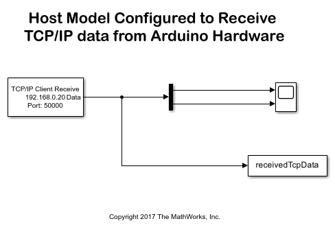
Double-click on the TCP/IP Receive block. Make sure that the IP address and port number are matching the Wi-Fi settings specified earlier to ensure that the data is received from the correct target hardware.
2. In the Simulation tab of the Simulink model, click Run. The scope should display the data (a ramp signal and a pulse) being sent from the target hardware.
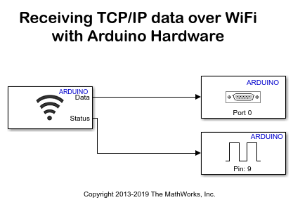
Task 3 - Receiving TCP/IP Data over Wi-Fi with Arduino Hardware
This task shows how to use Simulink Support Package for Arduino hardware to receive TCP/IP messages over Wi-Fi using an Arduino board.
Models involved in the demo
1. Target model running on the Arduino hardware: arduinomega2560_wifitcpreceive
2. Simulink host model: arduinowifi_tcp_hostsend
Run the model configured for the target on the hardware
1. Open the arduinomega2560_wifitcpreceive Simulink model.

2. Perform Task 1 if your Arduino board is not Arduino Mega 2560 hardware.
3. On the Hardware tab of the Simulink model, in the Mode section, select Run on board and then click Build, Deploy & Start.
Run the host model to send data to the target model
1. Open the arduinowifi_tcp_hostsend Simulink model.
Double-click on the TCP/IP Send block. Make sure that the IP address and port number are matching the Wi-Fi settings earlier specified to ensure that the data is sent to the correct target hardware.
2. The target model running on Arduino board will receive data from TCP/IP and send it back to the serial port for monitoring and debugging. You can use a serial monitor or hyperterminal on the host machine to watch the serial data coming back from the target.
3. Note that the WiFi TCP /IP Receive block is operating in blocking mode as Advanced > Wait until data received check box is checked. So when there is no incoming data you can see print statements in serial monitor or hyperterminal are slower.
4. In the Simulation tab of the Simulink model, click Run to start running the host model.
5. At this point, TCP/IP data is sent from the host to the target and serial data is sent back from the target to the host. You should be able to see the print statements in serial monitor or hyperterminal as soon as the target receives data i.e. no blocking.
Task 4 - Sending UDP Data over Wi-Fi Using Arduino Hardware
This example shows how to use Simulink Support Package for Arduino hardware to send UDP messages over Wi-Fi using an Arduino board.
Models involved in the demo
1. Target model running on the Arduino hardware: arduinomega2560_wifiudpsend
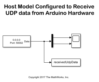
2. Simulink host model: arduinowifi_udp_hostreceive
Run the Model configured for the target on the hardware
1. Open the arduinomega2560_wifiudpsend Simulink model.

2. Perform Task 1 if your Arduino board is not Arduino Mega 2560 hardware.
3. On the Hardware tab of the Simulink model, in the Mode section, select Run on board and then click Build, Deploy & Start.
Run the host model to receive data from the target model
1. Open the arduinowifi_udp_hostreceive Simulink model.

Double-click on the UDP Receive block. Make sure that the port number is matching the Wi-Fi Shield settings specified earlier to ensure that the data is received from the correct target hardware.
2. In the Simulation tab of the Simulink model, click Run. The scope should display the data (a ramp signal and a pulse) being sent from the target hardware.
Task 5 - Receiving UDP Data over Wi-Fi Using Arduino Hardware
This task shows how to use Simulink Support Package for Arduino hardware to receive UDP messages over Wi-Fi using an Arduino board.
Models involved in the demo
1. Target model running on the Arduino Mega 2560: arduinomega2560_wifiudpreceive
2. Simulink host model: arduinowifi_udp_hostsend
Run the model configured for the target on the hardware
1. Open the arduinomega2560_wifiudpreceive Simulink model.
2. Perform Task 1 if your Arduino board is not Arduino Mega 2560 hardware.
3. In the Simulation tab of the Simulink model, click Run to run the model in External mode.
Run the host model to send data to the target model
1. Open the arduinowifi_udp_hostsend Simulink model.

Double-click on the UDP Send block. Make sure that the IP address and port number are matching the Wi-Fi settings specified earlier to ensure that the data is sent to the correct target hardware.
2. The target model running on the Arduino hardware will receive data from UDP. In External mode you can see the data and size displayed on the Display blocks. Initially when no data is received Data and Size both are 0.
3. In the Simulation tab of the Simulink model, click Run to start running the host model. Note that this model sends an array of int16 values.
4. At this point, UDP data is sent from the host to the target. You can see that the Data and Size output values changing corresponding to the received data.
See Also
Set Up a Wi-Fi TCP/IP Connection with Connected IO in Simulink
Select a Web Site
Choose a web site to get translated content where available and see local events and offers. Based on your location, we recommend that you select: United States.
You can also select a web site from the following list
Americas
- América Latina (Español)
- Canada (English)
- United States (English)
Europe
- Belgium (English)
- Denmark (English)
- Deutschland (Deutsch)
- España (Español)
- Finland (English)
- France (Français)
- Ireland (English)
- Italia (Italiano)
- Luxembourg (English)
- Netherlands (English)
- Norway (English)
- Österreich (Deutsch)
- Portugal (English)
- Sweden (English)
- Switzerland
- United Kingdom (English)