Simulate PWM Waveforms and Events
The PWM Write and PWM Interface blocks together enable a variety of pulse width modulation (PWM) waveforms and events to be simulated in an SoC model.
Internal Counter and Comparator Triggers
A PWM peripheral, at minimum, contains an internal timer with a counter and one or more comparators. The timer drives the counter on a continuous loop. The counter can operate in one of three modes:
Up – The counter increments up to the maximum value of the counter and then overflows, resetting to zero to start the count again. The counter forms a discrete sawtooth waveform.
Down – The counter decrements from the maximum value of the counter to zero and then underflows, resetting to the maximum value to start the count again. The counter forms a discrete sawtooth waveform.
Up-Down – The counter increments from zero to the maximum value of the counter and then the count decrements until the count reaches zero again. This cycle repeats to create a discrete triangular waveform.
The discrete waveforms generated by the timer and counter define the period and phase of the final PWM waveform. The counter is used as the reference for the comparators to modify the state of the output signal that becomes the PWM waveform.
The PWM contains a bank of comparators. The count value of each comparator gets
compared to the value of the counter. When the counter crosses that count value, the
comparator triggers. When a trigger occurs, the comparator can change the current output
state of the PWM waveform (for example, setting the output to 0).
Additionally, the trigger can generate an event that can be used by the Task Manager
block or other peripherals, such as the ADC Interface
block, to coordinate the input and output signals in the microcontroller unit
(MCU).
With the combination of the period and phase control of the internal timer and multiple comparators, you can create a variety of PWM waveforms to support your specific application requirements.
Phase-Offset Waveforms
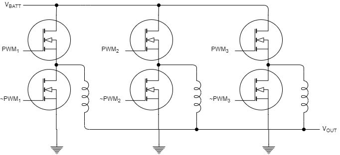
This example shows how to generate phase-offset PWM waveforms. You can use the phase-offset PWM waveform to drive MOSFETs in 3-phase switching power circuits, such as the interleaved DC/DC converter circuit shown in this figure. Each MOSFET pair gets driven by a PWM of the same frequency, where each branch phase is offset by 120°.
Model
This model contains the three PWM Interface blocks that each drive a separate PWM output. PWM 1 has a phase of 0°. You can open the PWM 2 and PWM 3 blocks and inspect the Phase > Phase offset in degree (0-360) parameters, which are 120° and 240°, respectively. All PWM Interface blocks in a model share an underlying synchronization allowing the PWM block output to be synchronized with offset phases.
open_system("pwm_3phase_interleaved_top.slx");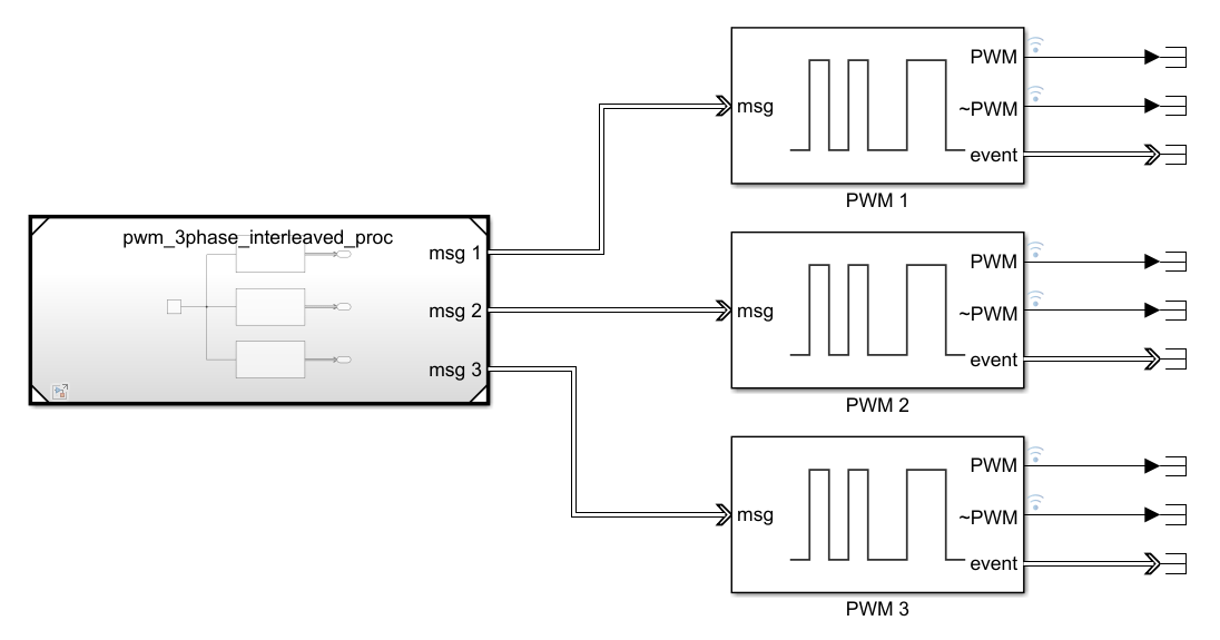
Results
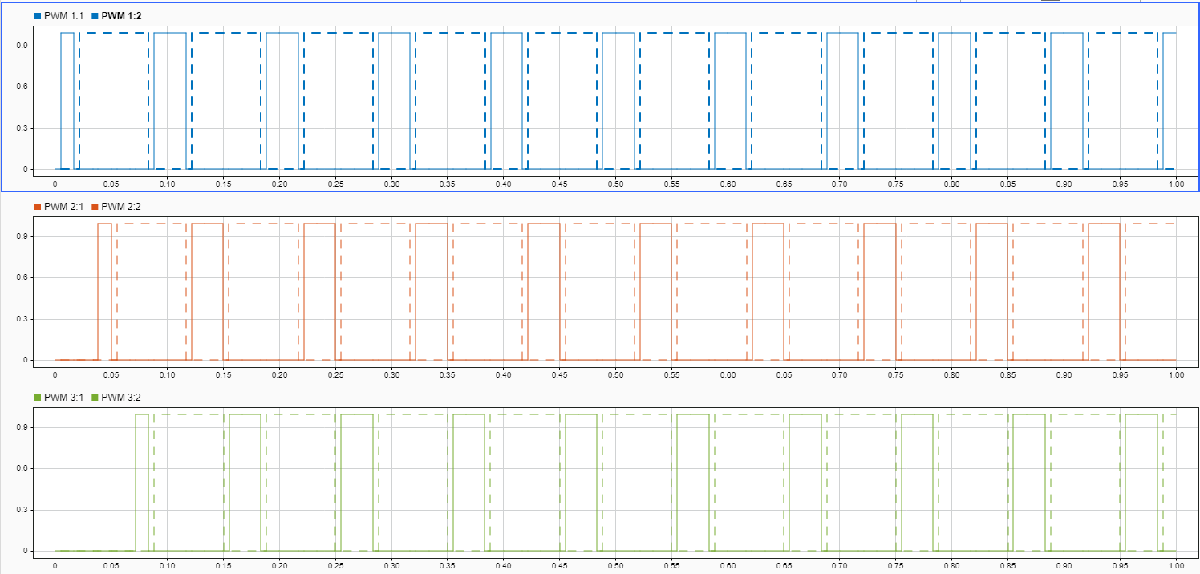
In the Simulation tab, click Run. When the simulation completes, open the Simulation Data Inspector to view the resulting signals from the PWM outputs. The signals show the PWM and PWM complement waveforms from each PWM Interface with each block offset by 120°.
Pulse Center Measurement Event from Waveform
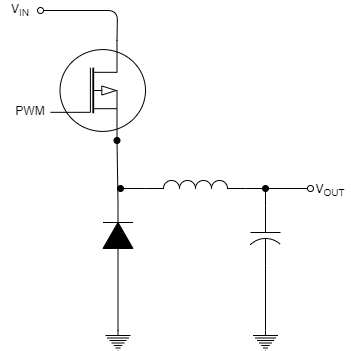
This example shows how to generate an event for a task in the pulse center of a PWM waveform. You can use the triggering of an event in the pulse center of a PWM waveform to get correct current measurements from ADCs in switching power circuits, such as the buck converter circuit shown in this figure. The model in this example shows a basic ADC sampling from a PWM-driven switch.
Model
This model uses two tasks. A timer-driven task sets the comparator values for the PWM Write block. The first comparator value, 0.5, sets the duty-cycle of the waveform produced by the PWM Interface block. The second comparator value, 0.25, sets the value of the comparator that triggers an event. In the PWM Interface block, the Counter mode parameter is set to Up, and the Event trigger mode parameter is set to Compare 2. These settings result in an event generated each time the internal PWM counter exceeds 25% of the total counter value. The output of the PWM Interface block drives a switch that samples from a Sine block. The event signal connects and triggers the ADC Interface block to sample the output of the switch at the center of the PWM pulse center. A event-driven task triggers on each event and uses the ADC Read block to sample the measured value.
open_system("soc_pwm_pulse_center_event_top")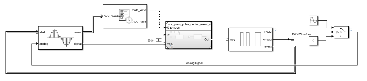
Results
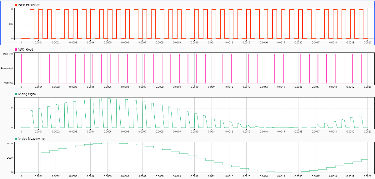
In the Simulation tab, click Run. When the simulation completes, open the Simulation Data Inspector to view the resulting signals from the PWM, ADC, and task event signals. From inspection, the ADC_Read event occurs in the pulse center of the PWM waveform. As a result, the Analog Measurement signal captures samples from the sine wave while ignoring the zero-valued gaps when the switch is off.
Symmetric PWM Waveform
This example shows how to generate a symmetric PWM waveform. In power switching circuits, such as the buck converter shown in this figure, symmetric PWM waveform signals can generate fewer harmonics in the output currents and voltages.

Model
This model contains a single task with a Sine block that sets the pulse width of a PWM waveform. Inspecting the connected PWM Interface block, the Main > Counter mode parameter is set to Up-Down, resulting in the internal counter forming a triangular wave. The PWM output > At start of period parameter is set to Low, and the PWM output > At compare 1 up count and PWM output > At compare 1 down count parameters are both set to Change. These settings result in a symmetrical waveform with the pulse center at the center of the PWM waveform.
open_system("soc_symmetric_pwm_waveform_top.slx");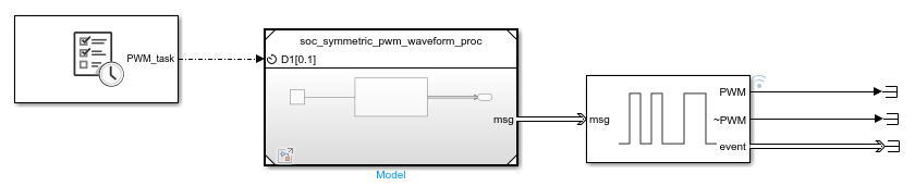
Results
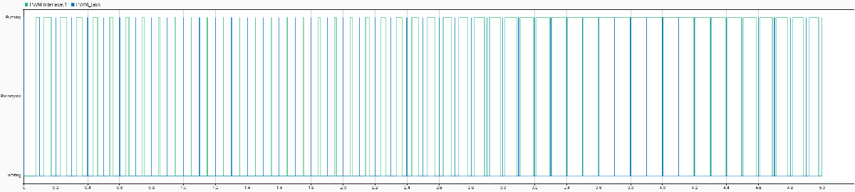
In the Simulation tab, click Run. When the simulation completes, open the Simulation Data Inspector to view the resulting signals from the PWM Interface block and PWM_task outputs. From inspection, the PWM Interface block output signal is symmetrical and centered in the PWM pulse.
See Also
PWM Interface | PWM Write | ADC Read | ADC Interface | Task Manager | Hardware Mapping
Related Topics
- Get Started with C2000 Multiprocessor Blocks on MCUs (C2000 Microcontroller Blockset)
- Integrate MCU Scheduling and Peripherals in Motor Control Application
- Partition Motor Control for Multiprocessor MCUs
External Websites
You can also select a web site from the following list:
Americas
- América Latina (Español)
- Canada (English)
- United States (English)
Europe
- Belgium (English)
- Denmark (English)
- Deutschland (Deutsch)
- España (Español)
- Finland (English)
- France (Français)
- Ireland (English)
- Italia (Italiano)
- Luxembourg (English)
- Netherlands (English)
- Norway (English)
- Österreich (Deutsch)
- Portugal (English)
- Sweden (English)
- Switzerland
- United Kingdom (English)