Measure Forces and Torques Acting at Joints
This example shows how to measure the actuator torque, constraint force, and total toque acting on a Revolute Joint block. The example uses a rack and pinion model.
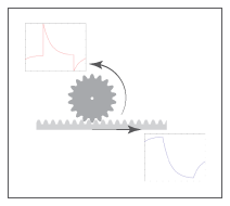
The joint blocks in Simscape™ Multibody™ have ports that measure force and torque. You can use these ports to compute and output various types of forces and torques acting directly at joints. For more information about forces and torques, see Force and Torque Sensing.
Open Model
To open the rack and pinion model, at the MATLAB® command prompt, enter:
openExample('sm/DocRackPinionExample','supportingFile','DocRackPinion.slx')
Sense Actuation Torque
The rack and pinion model uses a Signal Editor block to specify the actuator torque that drives the pinion. Because the Input filtering order property of the Simulink-PS Converter block is set to Second-order filtering, the block processes the input torque by smoothing any abrupt changes or discontinuities. To measure the actuator torque at the Revolute Joint block:
Double-click the Revolute Joint block to open the block dialog box. Under Z Revolute Primitive (Rz) > Sensing, select Actuator Torque. The block exposes the port t that outputs the actuator torque, which is a 3-D vector physical signal acting at the joint primitive.
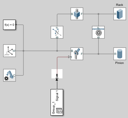
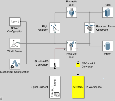
Add a PS-Simulink Converter block and To Workspace block to the model, then connect the blocks as shown in the figure.
Double-click the PS-Simulink Converter block. Set the Output signal unit parameter to
N*m.Simulate the model. The To Workspace block outputs the actuator torque to the simout variable in the MATLAB base workspace.
Plot the torque. At the MATLAB command prompt, enter:
figure;
plot(simout);
MATLAB plots the joint actuator torque. All but the z-component are zero throughout the simulation.
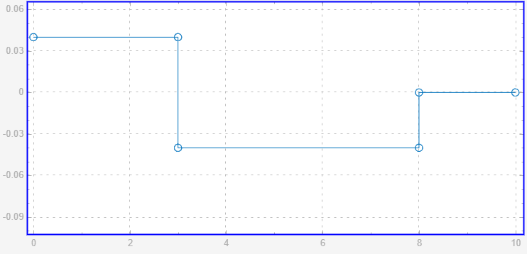
Compare the actuator torque plot to the input torque specified in the Signal Editor block. Neglecting any signal smoothing due to the second-order filtering, the two signals are identical. This figure shows the input torque.
Sense Constraint Forces
Joint constraint forces, which act normal to the joint primitive axes, restrict motion to the allotted degrees of freedom. In this model, the constraint forces acting at the Revolute Joint block resist the pull of gravity and keep the position of the pinion with respect to the world frame. To sense the constraint forces:
In the Mechanism Configuration block, set Uniform Gravity to
Constant. Ensure that the Gravity parameter is[0 0 -9.80665].In the Revolute Joint block, select Composite Force/Torque Sensing > Constraint Force. The block exposes the port fc. The port outputs constraint forces that act at the joint to maintain the translational constraints.
Under Z Revolute Primitive (Rz) > Sensing, clear Actuator Torque.
Double-click the PS-Simulink Converter block, set the Output signal unit parameter to
N. Ensure that the PS-Simulink Converter block connects to the port fc.Simulate the model, then plot the constraint forces. At the MATLAB command prompt, enter:
figure;
plot(simout);
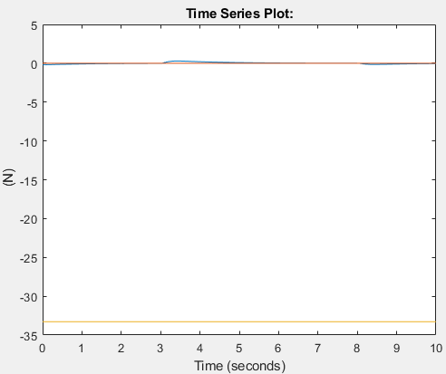
MATLAB plots the constraint force with respect to time. The x and y-components are zero throughout the simulation. The z component, which opposes the gravity vector, is the only component needed to hold the joint frames in place.
Tips:
In a Weld Joint block, the constraint forces ensure the base and follower frames remain fixed with respect to each other. You can place a Weld Joint block inside a body subsystem to measure the internal forces or torques acting in that body during a simulation. For an example of how you can do this in a double pendulum model, see Measure Joint Constraint Forces.
Sense Total Torques
The total force or torque is a sum of all forces or torques that act between the joint base and follower frames and includes contributions from the actuator, constraint, and internal forces or torques. To measure the total torque that acts at the revolute joint:
Double-click the Revolute Joint block to open the block diagram. Under Composite Force/Torque Sensing, select Total Torque. The block exposes the port tt. This port outputs the total torque that acts at the joint.
Under Composite Force/Torque Sensing, clear Constraint Force.
Double-click the PS-Simulink Converter block, set the Output signal unit parameter to
N*m. Ensure that the PS-Simulink Converter block connects to the port tt.Simulate the model.
Plot the total torque. At the MATLAB command prompt, enter:
figure;
plot(simout);
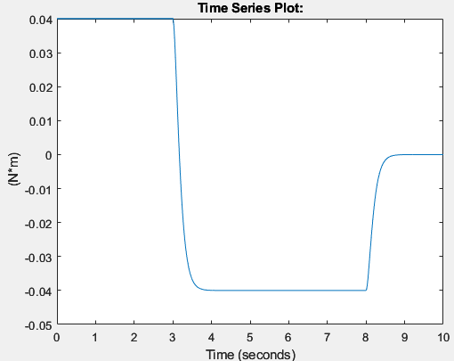
MATLAB plots the total torque, which is a 3-D vector, as a function of time. The x and y-components are zero throughout simulation. The z-component contains torque contributions from the actuation and internal torques.
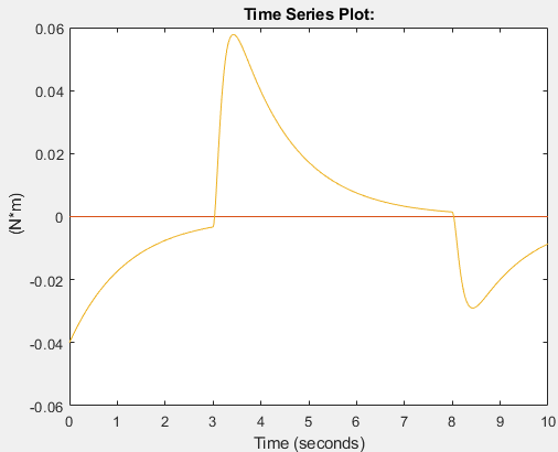
In the plot, the torque peaks are due to the actuator torque. These peaks decay with time due to the internal damping torques specified in the Revolute Joint block. The damping torques cause the energy dissipation evident in the transient portions of the total torque plot.