EtherCAT Protocol Motor Velocity Control with Accelnet Drive
This example shows how to control the velocity of a motor by using EtherCAT® communication. The example motor drive is from Copley Instruments. This drive uses the CIA-402 (Can In Automation 402) device profile common to many drives. The example can work with other CIA-402 EtherCAT drives if you generate an appropriate ENI file.
Requirements
This example is preconfigured to use an EtherCAT network that consists of the target computer as EtherCAT Main device and an Accelnet™ AEP 180-18 drive from Copley Controls as EtherCAT Subordinate device. Connect a supported brushless or brush motor to the drive. An example motor that works with this example is the SM231BE-NFLN from PARKER.
EtherCAT in Simulink® Real-Time™ requires a dedicated network port on the target computer that is reserved for EtherCAT use by using the Ethernet configuration tool. Configure the dedicated port for EtherCAT communication, not with an IP address. The dedicated port must be distinct from the port used for the Ethernet link between the development and target computers.
To test this model:
Connect the dedicated network port in the target computer to the EtherCAT IN port of the Accelnet drive.
Connect a motor to the Accelnet drive.
Make sure that the Accelnet drive is supplied with a 24-volt power supply.
Build and download the model onto the target.
For a complete example that configures the EtherCAT network, configures the EtherCAT main device node model, and builds then runs the real-time application, see EtherCAT Protocol Sequenced Writing CoE Subordinate Device Configuration Variables.
Open the Model
This model sends a varying velocity command to the drive.
The EtherCAT initialization block requires that the configuration ENI file is present in the current folder. Copy the example configuration file from the example folder to the current folder. To open the model, in the MATLAB® Command Window, type:
model = 'slrt_ex_ethercatVelocityControl';
open_system(model);
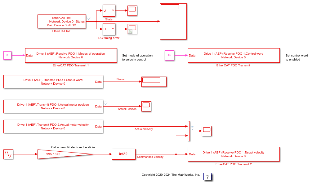
Figure 1: EtherCAT model for motor velocity control.
Configure the Model
Open the parameter dialog for the EtherCAT Init block and observe the pre-configured values. The EtherCAT subordinate devices that are daisy chained together with Ethernet cable is a Device, also referred to as an EtherCAT network. The Device Index selects one such chained EtherCAT network. The Ethernet Port Number identifies which Ethernet port to use to access that Device. The EtherCAT Init block connects these two so that other EtherCAT blocks use the Device Index to communicate with the subordinate devices on that EtherCAT network.
If you only have one connected network of EtherCAT subordinate devices, and you have only reserved one Ethernet port with the Ethernet configuration tool, use Device Index = 0 and Ethernet Port Number = 1.
Create an ENI file for a Different CIA-402 Drive
If you need to create a new ENI file, you need to use a third-party EtherCAT configurator such as TwinCAT 3 from Beckhoff that you install on a development computer. The EtherCAT configuration (ENI) file preconfigured for this model is CopleyMotorVelocityConfig.xml.
Each EtherCAT configuration file (ENI file) is specific to the exact network setup from which it was created (for example, the network discovered in step 1 of the configuration file creation process). The configuration file provided for this example is valid if and only if the EtherCAT network consists of one Accelnet drive from Copley Controls. If you have a different EtherCAT drive that uses the CIA-402 command set, this example still works, but you need to create a new ENI file that uses your drive.
For an overview of the process for creating an ENI file, see Configure EtherCAT Network by Using TwinCAT 3.
For this example, four receive PDO variables are defined in the configuration file and three are used in the three EtherCAT PDO Transmit blocks: Control Word, Modes of Operation, and Target Velocity. The fourth variable: Profile Target Position is used in example EtherCAT Protocol Motor Position Control with Accelnet Drive.
The Control Word PDO variable serves to control the state of the drive. The constant value 15 is given as input to the block to set the first 4 bits to 1 to enable the drive. Refer to the EtherCAT User Guide from Copley Controls for details on the bits mapping of this variable. This variable and bit mapping is in the CIA-402 standard set.
The Modes of Operation PDO variable serves to set the drive operating mode. The constant value 3 is given as input to the block to set the mode of the drive to
Profile Velocity mode. For details on supported modes of operation, see the Refer to the Copley Controls EtherCAT User Guide. This variable and bit mapping is in the CIA-402 standard set.The Target Velocity PDO variable serves to set the desired velocity. In this example, the velocity command at the input of the block can be tuned using the slider connected to the gain block parameter.
Three transmit PDO variables are also defined in the configuration file and used in the three EtherCAT PDO Receive blocks: Status Word, Actual Motor Velocity, and Actual Motor Position. Note that EtherCAT refers to variables that the subordinate device sets as transmit variables which are received by the target model.
The Status Word PDO variable indicates the current state of the drive.
The Actual Motor Velocity and Actual Motor Position PDO variables indicate the current values of the motor velocity and position as read in the drive.
Make sure that the required transmit and receive PDO variables are selected in the blocks as illustrated in Figure 1 before running the example. You could need to refresh these variables by opening the dialogs and selecting the current variable again.
Build, Download, and Run the Model
To build, download, and run the model:
In the Simulink Editor, from the targets list on the Real-Time tab, select the target computer on which to run the real-time application.
Click Run on Target.
If you open the host side scopes by double clicking each, data is relayed from the target back to the development computer and displayed.
Included in the model is the ability to control the peak amplitude of the velocity. With the Run on Target button, the slider is active and connected to the Amplitude constant block.
The model is preconfigured to run for 10 seconds. If you want to run the model longer, pull down the Run on Target menu and change the number on the bottom line. Press the green arrow to configure, build, and run.
Display the Target Computer Scopes
If you run the model using the Run on Target button, external mode is connected and you can double click the scope blocks and see the data on the host. Also, the slider is active in external mode.
The Scope output images are referred to by the name in the title bar for each image. Discussion follows each image.
Scope shows the target to subordinate device timing error as synchronization takes place using the bus shift method. The subordinate device is adjusted to match the target timing resulting in a damped wave showing good phase lock around 4.5 to 5 seconds. The hash is a manifestation of the QNX® execution scheduler and is what is expected. On this graph, 5000 is in nanoseconds, so this shows synchronization between 0 and -2 microseconds with residual random errors.
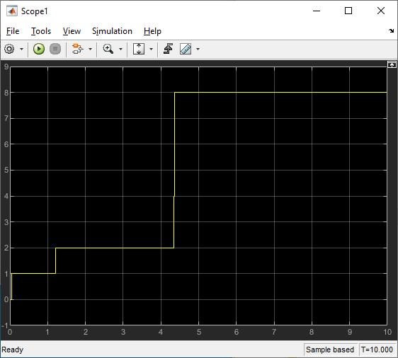
Scope1 shows the progression of states as the drive is initialized. Most of the time is taken to achieve time synchronization between target and EtherCAT subordinate devices. The SafeOp (=4) to Op (=8) state transition occurs after a short settling time once the timing error is below the allowed error.
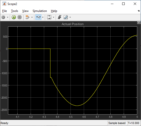
Scope2 shows the position of the motor which is a phase shifted version of the sine wave velocity that is sent to the motor. Note that the motor position does not change until the drive goes to Op state around 4.3 seconds.
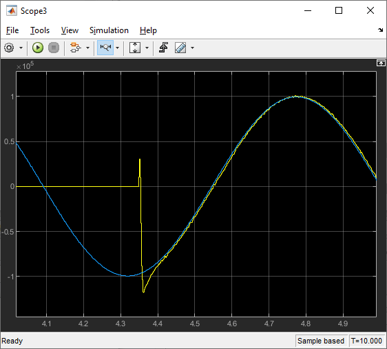
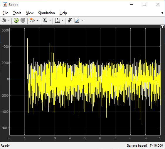
Scope3 shows the velocity that is sent to the drive and the velocity read back from the drive. The velocity does not change until the drive goes into Op state.
After running the model, you can also use the Simulation Data Inspector to view any signal that has been marked for signal logging. Signals marked for signal logging have a dot with two arcs above it in the model editor.
Observations to Notice
The velocity command for the motor is a low frequency sine wave. The actual velocity read back from the controller is delayed by several sample times and the actual position is out of phase by 90 degrees from the actual velocity, as expected for sinewave variation.
Stop and Close the Model
When the example completes its run, stop and close the model.
bdclose(model);
See Also
You can also select a web site from the following list
Americas
- América Latina (Español)
- Canada (English)
- United States (English)
Europe
- Belgium (English)
- Denmark (English)
- Deutschland (Deutsch)
- España (Español)
- Finland (English)
- France (Français)
- Ireland (English)
- Italia (Italiano)
- Luxembourg (English)
- Netherlands (English)
- Norway (English)
- Österreich (Deutsch)
- Portugal (English)
- Sweden (English)
- Switzerland
- United Kingdom (English)
Asia Pacific
- Australia (English)
- India (English)
- New Zealand (English)
- 中国
- 日本Japanese (日本語)
- 한국Korean (한국어)