Detect Integer Overflow and Division-by-Zero Errors
The following sections describe how to analyze the sldvdemo_cruise_control_fxp_fixed model for integer overflow and division-by-zero errors.
Analyze the Model
Open and check model for integer overflow and division-by-zero errors:
1. Open the sldvdemo_cruise_control_fxp_fixed model.
open_system('sldvdemo_cruise_control_fxp_fixed');2. On the Design Verifier tab, in the Prepare section, from the drop-down menu for the mode settings, click Settings.
3. In the Configuration Parameters dialog box, select Design Verifier > Design Error Detection.
4. On the Design Error Detection pane, select:
Integer overflow
Division by zero
5. In the Configuration Parameters dialog box, on the Diagnostics > Data Validity pane, set Signals > Wrap on overflow, Signals > Saturate on overflow.
6. Click OK to save these settings and close the Configuration Parameters dialog box.
7. In the Mode section, select Design Error Detection.
8. Click Detect Design Errors.
When the analysis is complete:
The software highlights the model with the analysis results.
The Simulink® Design Verifier™ Results dialog box opens and displays a summary of the analysis.
Review the Analysis Results
Review the Results on the Model
The derived ranges can help you understand the source of an error by identifying the possible signal values, as you can see by taking the following steps:
1. At the top level of the sldvdemo_cruise_control_fxp_fixed model, click the Fixed-Point Controller subsystem.
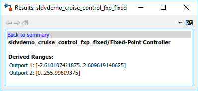
The Simulink Design Verifier Results window displays the derived range of possible signal values for the Outports, as calculated by the analysis:
The values of Outport 1 (throt) range from –2.6101 to 2.6096.
The values of Outport 2 (target) range from 0 to 255.9960.
2. Click the Outport blocks of the sldvdemo_cruise_control_fxp_fixed model to see the same signal bound values.
3. Open the Fixed-Point Controller subsystem.
Two objects in this subsystem are outlined in red. The PI Controller subsystem is outlined in green.
4. Click the Sum block, outlined in red, that provides the error input to the PI Controller subsystem.
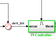
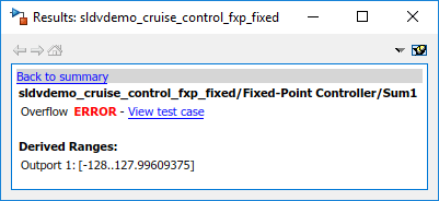
This Sum block can produce an overflow error. The analysis found a test case that can result in a computation where the output of the Sum block exceeds the range [–128..127.9960].
5. To more fully understand this error, click the two blocks that provide the inputs to the Sum block. In the Simulink Design Verifier Results window, view their derived ranges:
The third Outport from the Bus block has a range of [0..256].
The Outport from the Switch block has a range of [0..256].
You can see that the sum operation for these signal ranges can compute a value that exceeds the range [–128..128] for the Outport of the Sum block.
The analysis reports the overflow error on the Sum block. The analysis does not propagate this error and assumes that the Sum block output is within the valid range for any subsequent computations.
6. Click the PI Controller subsystem, outlined in green. None of the blocks in the PI Controller subsystem can produce overflow or division-by-zero errors. When the software analyzes the PI Controller subsystem, it ignores the overflow error from the Sum block and assumes that the inputs to the subsystem are valid.
Keep the sldvdemo_cruise_control_fxp_fixed model open. In the next section, you create the harness model to see the test case that generates the Sum block overflow error.
Review the Harness Model
To see the test cases that demonstrate the errors, generate the harness model from the Simulink Design Verifier Results window:
1. In the sldvdemo_cruise_control_fxp_fixed model, open the Fixed-Point Controller subsystem.
2. Click the Sum block, outlined in red, that provides the error input to the PI Controller subsystem.
The Simulink Design Verifier Results window displays information that an overflow error occurred.
3. In the Simulink Design Verifier Results window, click View counterexample.
The software creates a harness model containing the test case with the signal values that cause this overflow error.
In the harness model, the Signal Editor dialog box opens, with Counterexample_4 displayed.
4. Click the Run all button to simulate the model with this test case.
As expected, the simulation fails due to an overflow error at the Sum block in the Fixed-Point Controller subsystem.
For more information, see Use Harness Model for Test Simulations.
Review the Analysis Report
To view an HTML report containing detailed information about the analysis report for the sldvdemo_cruise_control_fxp_fixed model:
In the Simulink Design Verifier Results window, click HTML to see detailed analysis report.
The software generates a detailed analysis report that opens in a browser.
For the sldvdemo_cruise_control_fxp_fixed model, the Design Error Detection Objectives Status chapter of the report provides detailed results in two categories:
Objectives Valid — Model objects that did not produce errors
Objectives Falsified with Counterexamples — Model objects for which test cases generated errors
Model objects that have decision or condition outcomes receive dead logic detection. For more information on the complete list of model objects that have decision or condition objectives, see Model Objects That Receive Coverage (Simulink Coverage).
For more information, see Review Results from Analysis Report.
Note: Defect Checker automatically invokes dead logic, out of bound array access, division by zero, integer overflow, and specified minimum and maximum value violations checks. To specify checks set Defect Checker to ‘off’. For more information, see Detect Defects Using Optimized Checks.