Quick Loop Tuning of Feedback Loops in Control System Tuner
This example shows how to tune a Simulink® model of a control system to meet a specified bandwidth and specified stability margins in Control System Tuner, without explicitly creating tuning goals that capture these requirements. You can use a similar approach for quick loop tuning of control systems modeled in MATLAB®.
This example demonstrates how the Quick Loop Tuning option of Control System Tuner generates tuning goals from your crossover frequency and gain and phase margin specifications. This option lets you quickly set up SISO or MIMO feedback loops for tuning using a loop-shaping approach. The example also shows how to add further tuning requirements to the control system after using the Quick Loop Tuning option.
Quick Loop Tuning is the Control System Tuner equivalent
of the looptune command.
Set up the Model for Tuning
Open the Simulink model.
openExample('rct_distillation')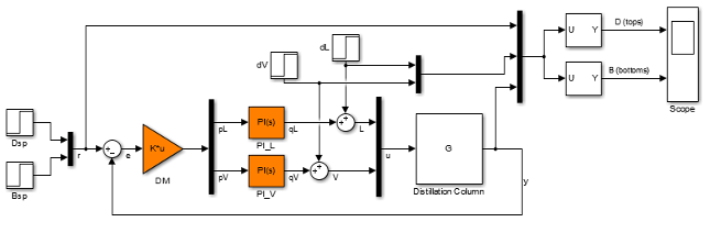
This model represents a distillation column, captured in the two-input, two-output
plant G. The tunable elements are the decoupling gain matrix
DM, and the two PI controllers, PI_L and
PI_V. (For more information about this model, see Decoupling Controller for a Distillation Column.)
Suppose your goal is to tune the MIMO feedback loop between r and
y to a bandwidth between 0.1 and 0.5 rad/s. Suppose you also require
a gain margin of 7 dB and a phase margin of 45 degrees. You can use the Quick
Loop Tuning option to quickly configure Control System Tuner for
these goals.
Open Control System Tuner. In the Simulink model window, in the Apps gallery, click Control System Tuner.
Designate the blocks you want to tune. In the Tuning tab of
Control System Tuner, click ![]() Select Blocks. In the Select tuned blocks dialog
box, click Add blocks. Then, select
Select Blocks. In the Select tuned blocks dialog
box, click Add blocks. Then, select DM,
PI_L, and PI_V for tuning. (For more information
about selecting tuned blocks, see Specify Blocks to Tune in Control System Tuner.)
The model is now ready to tune to the target bandwidth and stability margins.
Specify the Goals for Quick Loop Tuning
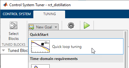
In the Tuning tab, select New Goal > Quick Loop Tuning.
For Quick Loop Tuning, you need to identify the actuator signals and sensor signals
that separate the plant portion of the control system from the controller, which for the
purpose of Quick Loop Tuning is the rest of the control system. The actuator signals are
the controller outputs that drive the plant, or the plant inputs. The sensor signals are
the measurements of plant output that feed back into the controller. In this control
system, the actuator signals are represented by the vector signal u,
and the sensor signals by the vector signal y.
In the Quick Loop Tuning dialog box, under Specify
actuator signals (controls), add the actuator signal, u.
Similarly, under Specify sensor signals (measurements), add the
sensor signal, y (For more information about specifying signals for
tuning, see Specify Goals for Interactive Tuning.)
Under Desired Goals, in the Target gain crossover
region field, enter the target bandwidth range, [0.1 0.5].
Enter the desired gain margin and phase margin in the corresponding fields.

Click OK. Control System Tuner automatically generates tuning goals that capture the desired goals you entered in the dialog box.

Examine the Automatically-Created Tuning Goals
In this example, Control System Tuner creates a Loop Shape Goal and a Margins Goal. If you had changed the pole-location settings in the Quick Loop Tuning dialog box, a Poles goal would also have been created.
Click ![]() Manage Goals to examine the automatically-created goals. By default,
the goals are active and designated as soft tuning goals.
Manage Goals to examine the automatically-created goals. By default,
the goals are active and designated as soft tuning goals.

You can double-click the tuning goals to examine their parameters, which are automatically computed and populated. You can also examine the graphical representations of the tuning goals. In the Tuning tab, examine the LoopTuning1_LoopShapeGoal plot.
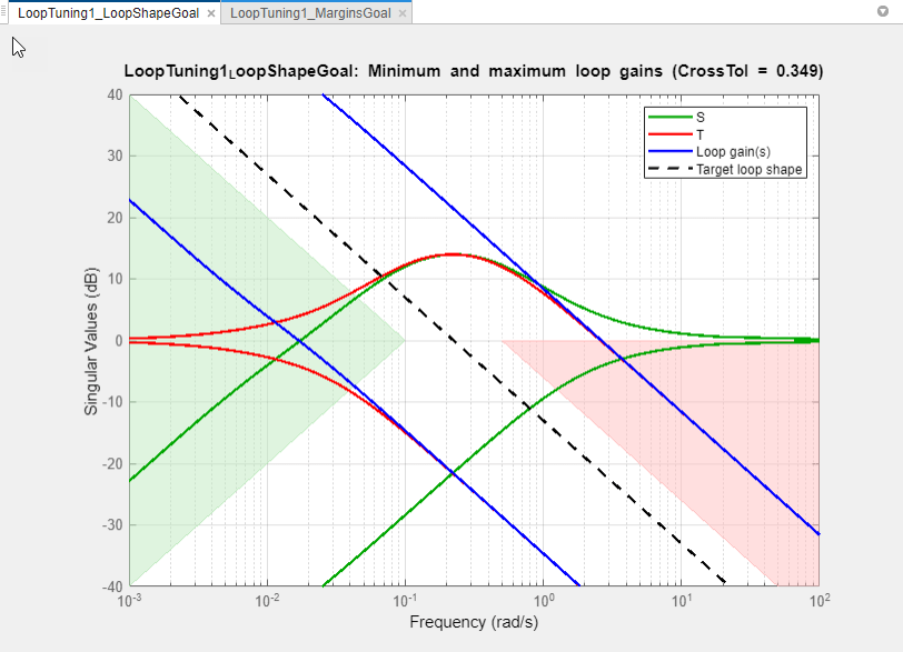
The target crossover range is expressed as a Loop Shape goal with an integrator
open-loop gain profile. The shaded areas of the graph show that the permitted crossover
range is [0.1 0.5] rad/s, as you specified in the Quick Loop
Tuning dialog box.
Similarly, your margin requirements are captured in the LoopTuning1_MarginsGoal plot.
Tune the Model
Click ![]() Tune to tune the model to meet the automatically-created tuning
goals. In the tuning goal plots, you can see that the requirements are satisfied.
Tune to tune the model to meet the automatically-created tuning
goals. In the tuning goal plots, you can see that the requirements are satisfied.
To create additional plots for examining other system responses, see Create Response Plots in Control System Tuner.
Change Design Requirements
If you want to change your design requirements after using Quick Loop Tuning, you can edit the automatically-created tuning goals and tune the model again. You can also create additional tuning goals.
For example, add a requirement that limits the response to a disturbance applied at
the plant inputs. Limit the response to a step command at dL and
dV at the outputs, y, to be well damped, to settle
in less than 20 seconds, and not exceed 4 in amplitude. Select New Goal > Rejection of step disturbances and enter appropriate values in the Step Rejection Goal dialog box. (For
more information about creating tuning goals, see Specify Goals for Interactive Tuning.)

You can now retune the model to meet all these tuning goals.