Load Data to Represent Nonvirtual Bus Input from Model Hierarchy
This example shows how to log data for a nonvirtual bus and how to use the logged data as external input for a model that receives the nonvirtual bus.
As you develop a referenced model, you can use logged data to test the referenced model independent of its parent model. Instead of the input data coming from the parent model, the input ports at the model interface load the external input data that you specify using the Input configuration parameter.
Open Example Model
Open the IterativeCounter project. The project opens the CounterSystem model at startup.
openProject("IterativeCounter");To update the line styles, update the model. On the Modeling tab of the Simulink® Toolstrip, click Update Model. You can use the line styles to visually identify buses. Alternatively, in the MATLAB® Command Window, enter this command.
set_param("CounterSystem",SimulationCommand="update")
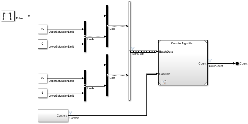
The Model block references a model named CounterAlgorithm. The referenced model receives two inputs:
BatchData— An array of buses that provides the data and the saturation limits of the counter. This array contains two nonvirtual buses namedData. Each of these nonvirtual buses contains a signal namedPulseand a nonvirtual bus namedLimits.Controls— A virtual bus that provides the signals that change the increment, reset the counter, and define an offset for the counter.
Both models use a data dictionary named BusTypes.sldd. The data dictionary contains the Simulink.Bus objects that define the nonvirtual buses named Data and Limits.
Log Data from Top Model Simulation
Suppose you want to test and refine the CounterAlgorithm model in isolation. You can use data logged from a simulation of the top model as input data when you simulate the referenced model as a top model.
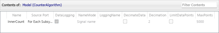
In the top model, the array of buses named BatchData, the bus named Controls, and the signal named OuterCount are marked for logging. In the referenced model, a signal named InnerCount is marked for logging.
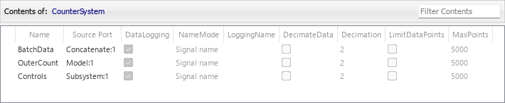
To view how the signals are logged, in the Simulink Toolstrip, on the Simulation tab, click Log Model Signals. In the Simulink Signal Logging Selector, Logging Mode is set to Log all signals as specified in model.
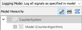
In the top model, data logging is enabled for BatchData, Controls, and OuterCount.
In the referenced model, data logging is enabled for InnerCount.
For more information, see View Logging Configuration Using the Signal Logging Selector.
Simulate CounterSystem.
out1 = sim("CounterSystem");After you simulate the model, the logged signals are available in the base workspace in the logsout property of the Simulink.SimulationOutput object named out1.
topOut = out1.logsout
topOut =
Simulink.SimulationData.Dataset 'logsout' with 4 elements

                         Name        BlockPath
                         __________  ________________________________________
    1  [1x1 Signal]      BatchData   CounterSystem/Concatenate
    2  [1x1 Signal]      OuterCount  CounterSystem/Model
    3  [1x1 Signal]      Controls    CounterSystem/Subsystem
    4  [1x1 Signal]      InnerCount  ...l|CounterAlgorithm/For Each Subsystem

  - Use braces { } to access, modify, or add elements using index.
Suppose you do not know the index of the element you want to inspect. To access signal data logged in Simulink.SimulationData.Dataset objects by element name, use the getElement object function.
batchOut = getElement(topOut,"BatchData")batchOut =
Simulink.SimulationData.Signal
Package: Simulink.SimulationData
Properties:
Name: 'BatchData'
PropagatedName: ''
BlockPath: [1×1 Simulink.SimulationData.BlockPath]
PortType: 'outport'
PortIndex: 1
Values: [2×1 struct]
Methods, Superclasses
Data for the array of buses is logged as a structure array in the Values property.
batchOutVals = batchOut.Values
batchOutVals=2×1 struct array with fields:
    Pulse
    Limits
This structure array contains a timeseries object for each element of each nonvirtual bus. For example, inspect the Pulse signals.
batchOutData1 = batchOutVals(1).Pulse
  timeseries

  Common Properties:
            Name: 'Pulse'
            Time: [301x1 double]
        TimeInfo: [1x1 tsdata.timemetadata]
            Data: [301x1 int32]
        DataInfo: [1x1 tsdata.datametadata]

  More properties, Methods
batchOutData2 = batchOutVals(2).Pulse
  timeseries

  Common Properties:
            Name: 'Pulse'
            Time: [301x1 double]
        TimeInfo: [1x1 tsdata.timemetadata]
            Data: [301x1 int32]
        DataInfo: [1x1 tsdata.datametadata]

  More properties, Methods
Simulate Model with Imported Data
Open CounterAlgorithm as a top model by clicking the Open As Top Model badge at the lower left corner of the Model block. Alternatively, in the MATLAB Command Window, enter this command.
open_system("CounterAlgorithm")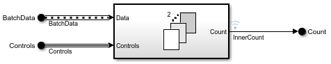
To use the referenced model as a top model, configure the referenced model to read the logged signal data through the root In Bus Element blocks.
To open the Root Inport Mapper:
In the Simulink Toolstrip, on the Modeling tab, click Model Settings.
In the Configuration Parameters dialog box that opens, select Data Import/Export.
Next to the Input box, click Connect Inputs.
To select the data to import:
In the Root Inport Mapper toolstrip, click From Workspace.
Select the logged data
topOut. Then, click OK.In the dialog box that opens, specify a MAT file to save signals to, such as
topOutData.mat.Click Save.
The software matches input data with input ports based on block name, block path, signal name, port order, or a custom algorithm. Because topOut contains logged data that uses signal names from the model, the best choice for a mapping criterion is the signal names. The software uses this criterion to try to match input data variable names to the names of the input signals.
To configure and check the mapping options:
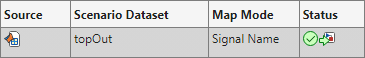
In the Scenarios pane, select the
topOutscenario data set.In the Root Inport Mapper toolstrip, in the Map Mode list, check that
Signal Nameis selected.Click Options and check that Update Model Automatically is selected.
Click
 .
.
When mapping data, the software evaluates input ports against the input data to determine compatibility. The Root Inport Mapper table reflects the status of this compatibility with a green check mark, orange warning triangle, or red error exclamation mark. In this example, the table shows a green status, indicating no compatibility issue.
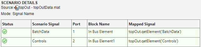
In the Scenarios pane, the Status entry for topOut includes icons that indicate that the model will simulate with this mapping of input data to input ports and that the mapping has been applied to the model.
In the Configuration Parameters dialog box, the Input configuration parameter specifies a comma-separated list.
![]()
This specification loads the input data for the ports.
The port named
BatchDatamaps to thetopOutelement namedBatchData. This element provides an array of structures of timeseries.The port named
Controlsmaps to thetopOutelement namedControls. This element provides a structure of timeseries.
When you close the Root Inport Mapper, optionally save the mapping and data as a scenario in an .mldatx file.
Simulate CounterAlgorithm.
out2 = sim("CounterAlgorithm");After you simulate the model, the logged signals are available in the base workspace in the logsout property of the Simulink.SimulationOutput object named out2.
counterOut = out2.logsout
counterOut =
Simulink.SimulationData.Dataset 'logsout' with 1 element

                         Name        BlockPath
                         __________  ___________________________________
    1  [1x1 Signal]      InnerCount  CounterAlgorithm/For Each Subsystem

  - Use braces { } to access, modify, or add elements using index.
Compare Logged Data
To compare the logged data, use the Simulation Data Inspector.
On the Simulation tab, click Data Inspector.
In the Simulation Data Inspector, click Compare.
In the Baseline list, select the most recent run for
CounterSystem.In the Compare to list, select the most recent run for
CounterAlgorithm.Click Compare.
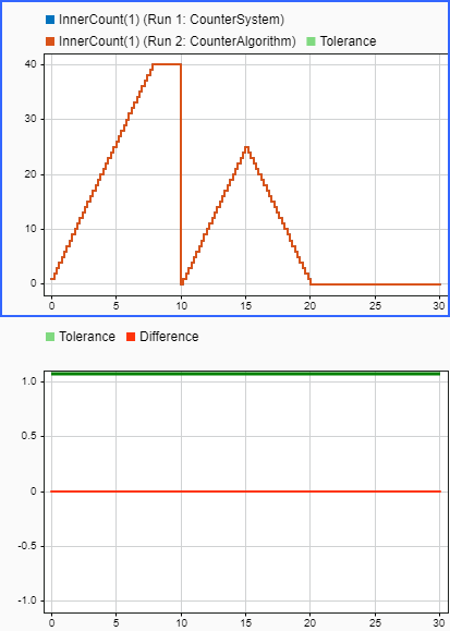
The Simulation Data Inspector compares the logged signal data for InnerData between the two simulations. The first simulation logs the data when you simulate CounterAlgorithm as a referenced model. The second simulation logs the data when you simulate CounterAlgorithm as a top model.
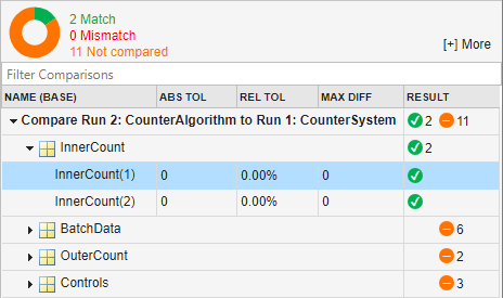
The results match for InnerCount. The other signals are not compared because the other signals are not part of the second simulation. In CounterAlgorithm, the only signal marked for logging is InnerCount.
The plots match between the two runs and show no difference in logged signal data.