Attach Buses to MATLAB Function Blocks
MATLAB Function can retrieve and output Simulink® buses. When you connect a bus to a MATLAB Function block, the block associates that signal with a structure. For more information on creating structures in MATLAB Function blocks, see Create Structures in MATLAB Function Blocks. You can also retrieve bus data from Data Store Memory blocks. For more information on using buses and Data Store Memory blocks, see Data Stores with Buses and Arrays of Buses.
Note
MATLAB Function blocks convert input virtual buses to nonvirtual buses and output only nonvirtual buses.
Read and Write Buses with a MATLAB Function Block
This example uses structures in a MATLAB Function block to read and write to Simulink buses.

Open the emldemo_bus_struct model. The inbus port of the MATLAB Function block connects to a bus and the outbus and outbus1 ports output buses. The input signal comes from the Bus Creator block MainBusCreator, which bundles the signals ele1, ele2, and ele3. The signal ele3 is the output of another Bus Creator block, SubBusCreator, which bundles the signals a1 and a2. The outbus and outbus1 ports connect to Bus Selector blocks that, in turn, connect to Display blocks.
Simulink.Bus Objects Defined In Simulink
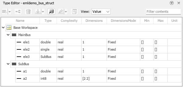
In this example, each structure in the MATLAB Function block must correspond to a Simulink.Bus object. Consequentially, the structures in the block inherit the same properties as the Simulink.Bus object they are assigned to, including the number, name, type, and sequence of fields. This model defines two Simulink.Bus objects, MainBus and SubBus. Loading the model loads the buses into the base workspace. You can view the bus definitions and their elements in the Type Editor. In the Modeling tab, in the Design section, click Type Editor. In the Type Editor, set View to Value.
The model uses these buses in the Bus Creator blocks. MainBusCreator outputs a bus with the same type as MainBus, and SubBusCreator outputs a bus with the same type as SubBus.
Structure Definitions in the MATLAB Function Block
Inspect the function fcn by opening the MATLAB Function block. The code defines a local variable mystruct using the struct function, and uses this local variable to initialize the value of the first output, outbus. The function initializes the second output, outbus1, to the value of the ele3 field in inbus.
function [outbus, outbus1] = fcn(inbus)
substruct.a1 = inbus.ele3.a1;
substruct.a2 = int8([1 2;3 4]);
mystruct = struct('ele1',20.5, 'ele2', single(100), 'ele3', substruct);
outbus = mystruct;
outbus.ele3.a2 = 2*(substruct.a2);
outbus1 = inbus.ele3;
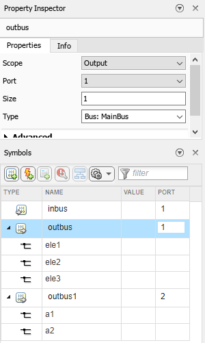
View the definitions of the structures in the MATLAB Function block. In the Function tab, click Edit Data. Click a variable to see its properties in the Property Inspector. In this example, inbus inherits its type, and therefore the Symbols pane does not display the structure elements for inbus. By contrast, the Type property of the output variables are set to buses, and the Symbols pane shows the bus elements associated with each variable. Expand the lists of the output structures in the Symbols pane to view the fields.
Write Buses from Data Store Memory to a MATLAB Function Block
This example shows how to use bus data stored in a data store as an input to a MATLAB Function block.

Capture the Bus Data in a Data Store Memory Block
In this example, the Bus Creator block MainBusCreator creates a bus called MainBus because the Output data type parameter is Bus: MainBus. The Data Store Write block then uses the Data store name parameter to write the bus data to a data store named inbus.
To store the bus data from the Data Store Write block, the model includes a Data Store Memory block. In the Data Store Memory block, the Data store name parameter is inbus, the name of the data store defined by the Data Store Write block. The Data type parameter is Bus: MainBus, the data type specified by the MainBusCreator block.

Define the Data Store Memory Variable
To capture the data store in a variable, the MATLAB Function block uses variables that have the Scope property set to Data Store Memory. The function then defines the variable as a global variable with the name of the data store, which is inbus. Double-click the MATLAB Function block to examine the code.
function [outbus, outbus1] = fcn
global inbus;
substruct.a1 = inbus.ele3.a1;
substruct.a2 = int8([1 2;3 4]);
mystruct = struct('ele1',20.5, 'ele2', single(100), 'ele3', substruct);
outbus = mystruct;
outbus.ele3.a2 = 2*(substruct.a2);
outbus1 = inbus.ele3;
The inbus variable inherits its properties from the data store. To change its properties, you must directly change the properties of the signal sent to the Data Store Write block.