Annotate Models
You can use annotations to label your block diagram and provide information about its contents in the canvas. You can also add annotations that perform an action when you click them.
You can create a text annotation or an image annotation.
Text annotations can contain any combination of these elements:
Text
Images
Equations generated using LaTeX and MathML commands
Hyperlinks that open a website or run MATLAB® functions
Image annotations can only contain images. Use image annotations when you want to resize or move an image independently from text.
To annotate models programmatically, see Create and Edit Annotations Programmatically.
To provide extensive background information or instructions for a model without cluttering the canvas, you can write notes. See Write In-Model Documentation Using Notes for details.
Create Text Annotations
To create a text annotation:
Double-click the canvas where you want the annotation. The quick insert menu opens. The default option in the quick insert menu is Create Annotation.
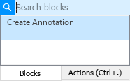
Press Enter.
Type the annotation text.
Use the formatting toolbar to edit the text font, font size, font color, or highlight color.
To create a bulleted or ordered list, select the annotation text, right-click the selection, and then select Paragraph > Bullets or Paragraph > Numbering.
To align the annotation text, select the annotation text, right-click the selection, and then select Paragraph > Alignment.
To add an image, table, or equation to the annotation, in the formatting toolbar, click Insert Image
 , Insert Table
  , or Insert Equation
  . For more information about adding equations, see Add Equations to Text Annotations.
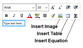
To add a hyperlink, in the annotation, select the content that you want to make interactive. Right-click the selected content and select Hyperlink or press Ctrl+K. For more information about adding hyperlinks, see Add Hyperlinks to Annotations.
Tip
Alternatively, to create a text annotation, in the Simulink® Editor palette at the left edge of the model window, click Annotation
![]() . Then, click the canvas and type the annotation
text.
. Then, click the canvas and type the annotation
text.
To create an annotation using text from another application, drag the text from the application to the canvas.
To paste text from the clipboard into an annotation, right-click the canvas, click the arrow
![]() , and then click the Paste button
, and then click the Paste button
![]() .
.
To create a copy of the annotation, press Ctrl while you click and drag the annotation.
Add Equations to Text Annotations
To add an equation to a text annotation:
In the formatting toolbar, click Insert Equation.

In the Edit Equation dialog box, enter LaTeX or MathML code to generate equations. For supported LaTeX commands, see Insert LaTeX Equation.
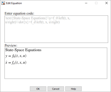
To format the equation, use the formatting toolbar. You can change the text font, font size, font color, or highlight color.
To edit equation code, double-click the equation in the annotation.
Add Symbols to Text Annotations
To add symbols or Greek letters into the annotation text, type the TeX formatting command that generates these symbols into the annotation text.
Add supported TeX commands to your annotation. For example, add this text:
\sigma \kappa \mu
With the annotation selected, or with the text cursor in the annotation, in the Property Inspector, under Appearance, select Enable TeX commands.
When you click outside the annotation, the TeX commands appear as symbols in the annotation.
The table shows the TeX characters that you can type directly into the text of a Simulink annotation.
| Supported TeX Characters | ||
|---|---|---|
|
|
|
Create Image Annotations
You can use image annotations to add images to the Simulink canvas that convey information about the model or function as background images for the entire block diagram or for groups of model elements.
To add an image to your model:
In the Simulink Editor palette at the left edge of the model window, click Image.

Click the canvas at the location where you want the image.

Double-click the image icon in the canvas.
In the file locator that opens, find and open the image you want to add.
If the image that appears in the canvas is too large or too small, to resize it, click and drag one of its corners.
Tip
To resize proportionally, press Shift as you drag.
If you resize an image, you can reset it to its original size. Right-click the image, and then click the Restore Size button
 .
.
To create an annotation using an image from another application, drag the image from the application to the canvas.
To create an annotation using an image file, drag the image file to the canvas.
To paste an image from the clipboard into an annotation, right-click the canvas, click the arrow
![]() , and then click the Paste button
, and then click the Paste button
![]() .
.
To include an image, such as your company logo, in every new model, add the image to your default template. See Create Template from Model.
To create a copy of the annotation, press Ctrl while you click and drag the annotation.
To change the image to a different image, double-click the image. In the file locator that opens, find and open the new image you want to use.
Associate Annotations with Blocks and Areas
You can add a line between an annotation and a block or area in a model. These annotation connectors attach dynamically at both ends, so that they move and resize as necessary to maintain the connection.
To add a connector:
Pause the cursor over the annotation outline where you want the line to start.
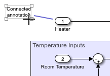
When the cursor is a crosshair, drag the line to the block or area where you want the line to end.

To specify the color or width of an annotation connector, right-click the connector and use the Format menu.
Hide Annotations
You cannot hide an annotation, but you can convert an annotation to markup and then hide the markup.
To convert the annotation to markup:
Right-click the annotation, and under Visibility, select Markup.
Note
Markup has a light blue background, regardless of the background color you set. If you change markup to an annotation, the annotation returns to the background color you set.
To change markup back to an annotation, right-click the markup, and under Visibility, select Annotation.
To hide the markup in your model, in the Format tab, click Show Markup.
To display hidden markup annotations, in the Format tab, click Show Markup.
In a model reference hierarchy, Show Markup and Hide Markup apply only to the current model reference level.
Add Hyperlinks to Annotations
You can add hyperlinks to annotations that open web pages or run MATLAB functions.
To add a hyperlink to an annotation:
In the annotation, select the content that you want to make interactive.
Right-click and select Hyperlink from the context menu.
In the Hyperlink dialog box, do one of these actions:
Select URL Address and enter the web address in the Code box.
Select MATLAB Code and enter MATLAB functions in the Code box.
Click OK.
When you click the annotation, the web page you specified opens or the code you specified runs.
You can also associate text or image annotations with callback functions that run:
When you load the model containing the annotation (load function)
When you programmatically delete an annotation or when you interactively or programmatically close the model (delete function).
To associate a load function with an annotation, programmatically set the
LoadFcnproperty of theSimulink.Annotationobject to the desired function.To associate a delete function with an annotation, programmatically set the
DeleteFcnproperty of theSimulink.Annotationobject to the desired function.
For example, add an annotation to your model that modifies the value of the variable
x when you load or close the model:
Add an annotation to your model with the text
increment x.To initialize
x, enter this command in the MATLAB Command Window.x=3;
To get the annotation programmatically, in your model, select the annotation. Then, enter this command.
an=getCurrentAnnotation;
To specify the load function for the annotation, enter this command.
an.LoadFcn="x=x+1;";To specify the delete function for the annotation, enter this command.
an.DeleteFcn="x=x-1;";Save the model.
Close the model and check the value of
xin the Workspace panel. The value ofxis2because the delete function has decreased the value by1.Reopen the model and check the value of
xin the Workspace panel. The value ofxis3because the load function has increased the value by1.