Perform Fog Rectification by Using Neighborhood Processing Subsystem Blocks
This example shows how to remove fog from images captured under foggy conditions. Such images have low visibility and poor contrast, which leads to poor vision algorithm performance. Fog rectification is an important step for applications in autonomous driving and object recognition because it improves input image quality.
For more information about fog rectification algorithms, see Fog Rectification (Vision HDL Toolbox).
Inspect Model
Open the model.
mdl = "FogRectificationNeighborhoodExample";
open_system(mdl);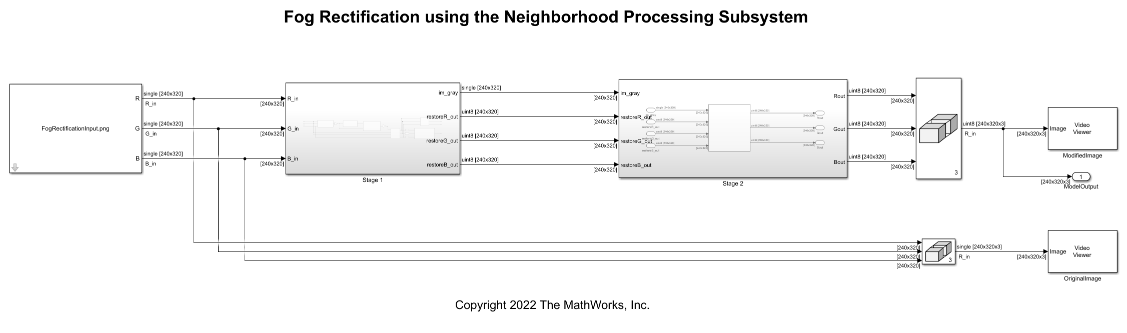
The model references an input image and passes the red, blue, and green channels of that image to the Stage 1 subsystem, which performs fog removal. This process estimates the amount of fog in each pixel and creates an image with the fog removed. This image has a reduced range of intensity for each color channel, so the Stage 2 subsystem performs contrast enhancement to stretch the dynamic range of the image and improve the contrast between features of the image. The result is a defogged image with high contrast.
Inspect Fog Removal
Open the Stage 1 subsystem, which performs fog removal in these steps.
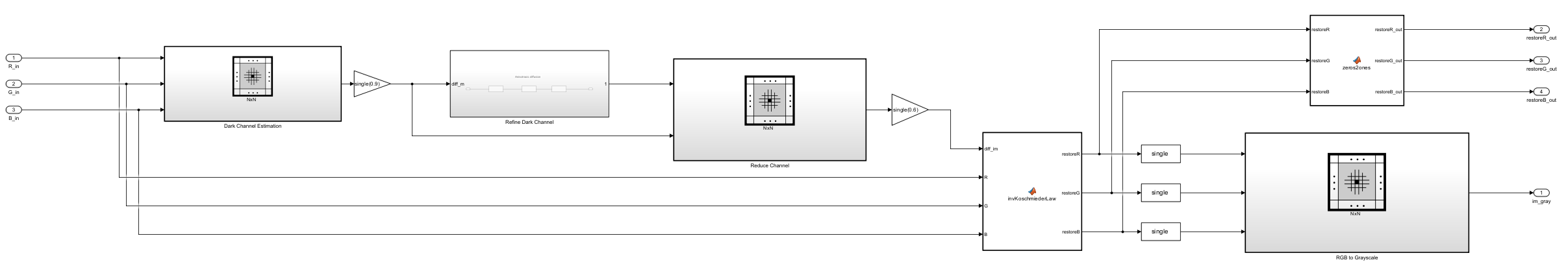
1. Dark Channel Estimation — The pixels that represent the non-sky region of an image have low intensities in at least one color component. These low intensities form a dark channel. In a normalized, fog-free image, the intensity of dark channel pixels is nearly zero. In a foggy image, the fog causes the intensity of dark channel pixels to be relatively high. The Dark Channel Estimation subsystem estimates the dark channel by finding the pixel-wise minimum across all three components of the input image where .
The Dark Channel Estimation subsystem contains these blocks.
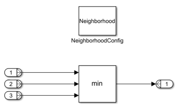
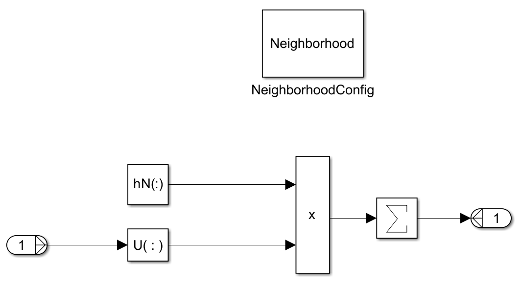
The Neighborhood Processing Subsystem uses a 1-by-1 neighborhood and calculates the minimum value across the color channels by using a Min block. This creates a two-dimensional dark channel output matrix consisting of the lowest channel intensity for each input image pixel.
2. Airlight Map Calculation — The white effect fog produces in an image is known as airlight. Airlight map calculation multiplies the dark channel by a value , representing the amount of haze to remove. is a value between 0 and 1; a higher value removes more fog in the final image.
The model uses a Gain block with a value of 0.9 for airlight map calculation.
3. Airlight Map Refinement — The Refine Dark Channel subsystem reduces visual noise in the image. The subsystem contains a sequence of three identical Neighborhood Processing Subsystem blocks.
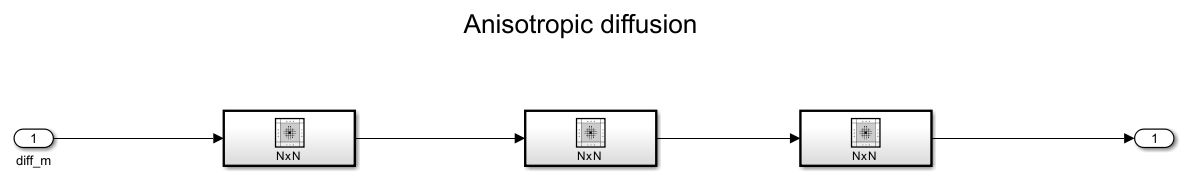
Each Neighborhood Processing Subsystem implements anisotropic diffusion.
By repeating this process three times, the Refine Dark Channel subsystem reduces visual noise and strengthens the clarity of details in the image. This yields a refined image, .
4. Restoration — This step counteracts over-smoothing from the previous step by implementing these equations.
The value represents the mid-line of changing the dark regions of the airlight map from dark to bright values. This example uses an empirically derived value of .
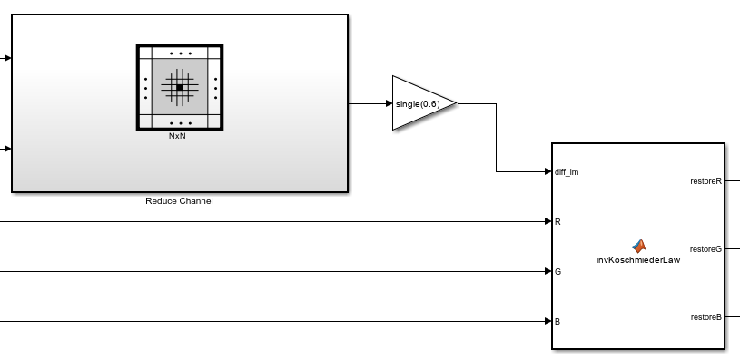
The model uses a Min block inside a Neighborhood Processing Subsystem to derive the minimum between the airlight map and the refined image, then uses a Gain block to multiply that matrix by 0.6.
The MATLAB Function block subtracts the reduced airlight map from the original input image, then multiplies by the factor . This yields , which represents the defogged image.
5. RGB to Grayscale Conversion — The last Neighborhood Processing Subsystem in Stage 1, RGB to Grayscale, converts to a grayscale image, .
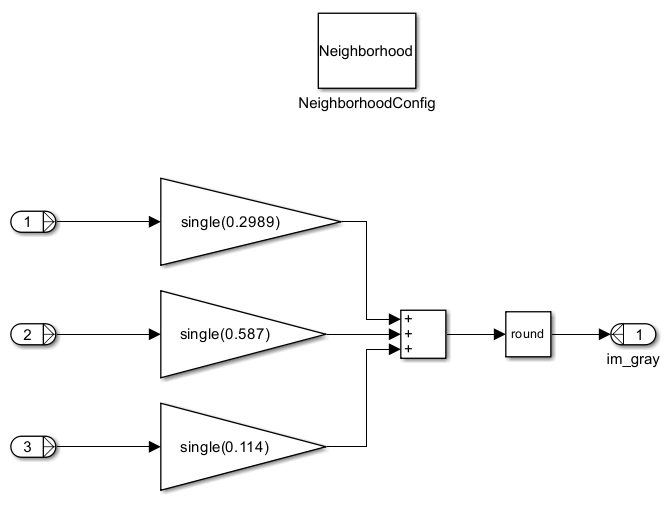
This grayscale image is necessary for the next stage of the model.
Inspect Contrast Enhancement
The Stage 1 subsystem produces an image with the fog removed, but the output image has a limited dynamic range compared to the input image. The Stage 2 subsystem stretches the output image brightness values to span the dynamic range of the input image. This improves contrast between features of the output image.
Return to the root model and open the Stage 2 subsystem.
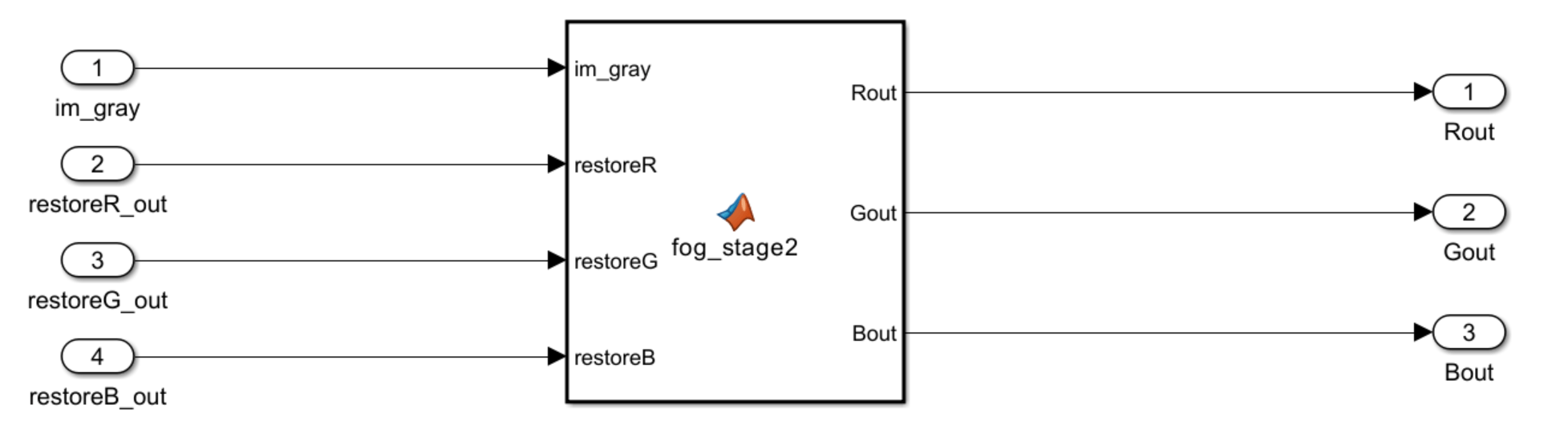
The subsystem uses a MATLAB Function block to perform contrast enhancement. For information about the calculations involved in this step, see Fog Rectification (Vision HDL Toolbox).
Simulate Model
Simulate the model.
simout = sim(mdl);
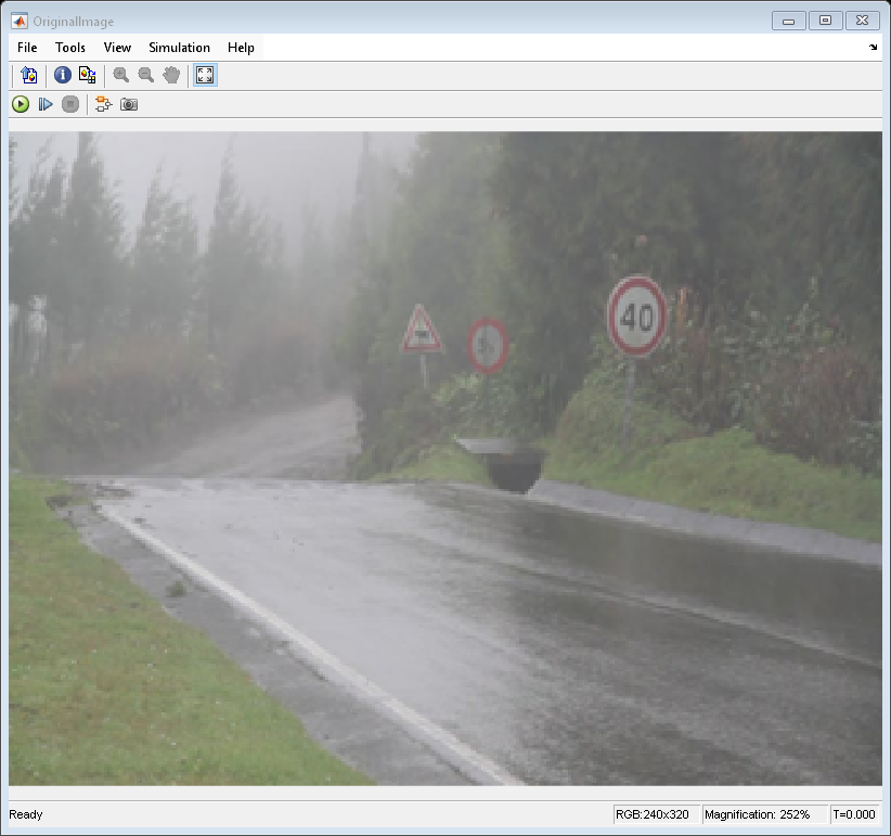
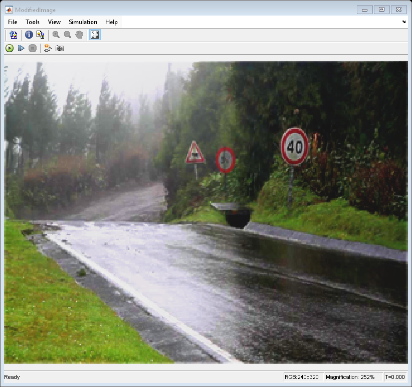
The model outputs the original image and the modified image. The modified image lacks the fog from the original image and has high contrast.
See Also
Neighborhood Processing Subsystem | Fog Rectification (Vision HDL Toolbox)
Topics
- Convert RGB Image to Grayscale by Using a Pixel Processing Subsystem Block
- Calculate Optical Flow by Using Neighborhood Processing Subsystem Blocks
- Perform Edge Detection by Using a Neighborhood Processing Subsystem Block
- Perform Corner Detection by Using Neighborhood Processing Subsystem Blocks
- Generate HDL Code from Frame-Based Models by Using Neighborhood Modeling Methods (HDL Coder)
- Use Neighborhood, Reduction, and Iterator Patterns with a Frame-Based Model or Function for HDL Code Generation (HDL Coder)