Concurrent Execution
Specify tasks, triggers, and nodes for concurrent execution of Simulink model
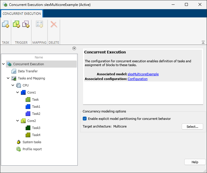
Description
Use the Concurrent Execution tool to specify tasks, triggers, and nodes for concurrent execution of a Simulink® model.
After you configure the Simulink model, you can use the Concurrent Execution tool to:
Add, edit, and delete periodic triggers and tasks.
Add, edit, and delete aperiodic triggers and tasks.
Explicitly assign partitions to execution elements or blocks in your model.
Specify how to handle data transfers between concurrently executing partitions.
Open the Concurrent Execution
Simulink Toolstrip: You can only open the Concurrent Execution tool if you select the Allow tasks to execute concurrently on target parameter in the Configuration Parameters dialog box. To open the tool:
Open the Configuration Parameters dialog box, then select Solver in the left pane.
Expand the Solver details section and select Allow tasks to execute concurrently on target.
This option is visible only if Solver Type is
Fixed Stepand Periodic sample time constraint isUnconstrained.Click Configure Tasks.
Examples
Parameters
Concurrent Execution
Select this check box to enable manual mapping of tasks to blocks. When you select this check box, you:
Enable custom task-to-block mappings. The node name changes to Tasks and Mapping label and the icon changes.
Disable the Automatically handle rate transition for data transfer check box in the Data Transfer pane.
Clear this check box to use rate-based tasks. Clear this check box to:
Disable custom task-to-block mappings. The node name changes to (Ignored) Tasks and Mapping.
Enable the Automatically handle rate transition for data transfer check box in the Data Transfer pane.
Programmatic Use
Parameter:
ExplicitPartitioning |
Values:
on | off |
Default:
off |
Choose from a set of predefined architectures in Simulink or a custom architecture. For more information on custom architectures, see Define a Custom Architecture File.
Clear this check box to reset existing target property settings to their default.
Data Transfer
Select the data transfer mode to use for synchronous signals:
Select
Ensure data integrity onlyto ensure maximum data integrity during data transfer.Select
Ensure deterministic transfer (maximum delay)to ensure maximum capacity during data transfer.Select
Ensure deterministic transfer (minimum delay)to ensure minimum capacity during data transfer.
Dependencies
To enable this parameter, select Enable explicit model partitioning for concurrent behavior.
Select the data transfer mode to use for continuous signals:
Select
Ensure data integrity onlyto ensure maximum data integrity during data transfer.Select
Ensure deterministic transfer (maximum
                    delay)
to ensure maximum capacity during data transfer.Select
Ensure deterministic transfer (minimum
                    delay)
to ensure minimum capacity during data transfer.
Dependencies
To enable this parameter, select Enable explicit model partitioning for concurrent behavior.
Select the extrapolation method to use to configure continuous-to-continuous task transitions:
Select
Noneto not use an extrapolation method for task transitions.Select
Zero Order Holdto use the zero order hold extrapolation method for extrapolation task transitions.Select
Linearto use the linear extrapolation method for extrapolation task transitions.Select
Quadraticto use the quadratic extrapolation method for extrapolation task transitions.
Dependencies
To enable this parameter, select Enable explicit model partitioning for concurrent behavior.
Tasks and Mapping
Software Node
Enter a unique character vector to identify the software node. This value must be a valid MATLAB® variable.
Hardware Node
Enter a unique character vector to identify the hardware node. This value must be a valid MATLAB variable.
Enter a value to specify the clock frequency of hardware node.
Click the color picker button to select a color for the task icon.
The hardware node icon appears in the left pane.
Task
Add a task to software node by clicking the Add task button,
![]() .
.
Enter a unique character vector to identify the task configuration. This value must be a valid MATLAB variable.
Enter a positive real or ratio value.
You can parameterize this value by using MATLAB expression character vectors as values.
Click the color picker button to select a color for the task icon.
The task icon appears on the top left of the Model block to which the task is assigned.
After you add a task, the software automatically assigns a color to the task icon, up to six colors. When the current list of colors is exhausted, the software reassigns previously used colors to the new tasks, starting with the first color assigned. If you select a different color for an icon and then use the software to automatically assign colors, the software assigns a preselected color.
Periodic Trigger
Add a periodic trigger to software node by clicking the Add periodic trigger
button, ![]() .
.
Enter a unique character vector to identify the periodic trigger configuration. This value must be a valid MATLAB variable.
Enter a positive real or ratio value.
You can parameterize this value by using MATLAB expression character vectors as values.
Click the color picker button to select a color for the periodic trigger icon.
Specify the XML-format custom architecture template file for code generation to use for the task, periodic trigger, or aperiodic triggers.
Aperiodic Trigger (Interrupt)
Add an aperiodic trigger to software node by clicking the Add aperiodic trigger
button, ![]() .
.
Enter a unique character vector to identify the interrupt-driven task configuration. This value must be a valid MATLAB variable.
Click the color picker button to select a color for the task icon.
The interrupt icon appears on the top left of the Model block to which the task is assigned.
As you add an interrupt, the software automatically assigns a color to the interrupt icon, up to six colors. When the current list of colors is exhausted, the software reassigns previously used colors to the new interrupts, starting with the first color assigned. If you select a different color for an icon and then use the software to automatically assign colors, the software assigns a preselected color.
Select the trigger source for the interrupt-driven task:
For Linux® or VxWorks®, set this parameter to
POSIX Signal (Linux/VxWorks 6.x).For Windows® systems, set this parameter to
Event
                      (Windows)
.
Enter the POSIX signal number for the trigger source.
Dependencies
To enable this parameter, set Aperiodic trigger
source to
POSIX Signal (Linux/VxWorks 6.x).
Specify the name of the trigger source event.
Aperiodic trigger source > Event (Windows) enables this parameter.
Dependencies
To enable this parameter, set Aperiodic trigger
source to Event (Windows).
System tasks
Task
Specify the name for the periodic system task configuration.
To change the name, period, or color of this task, right-click the task node and select Convert to editable periodic task.
Enter a positive real or ratio value.
To change the name, period, or color of this task, right-click the task node and select Convert to editable periodic task.
Minimum:
0
Click the color picker button to select a color for the task icon.
The task icon appears on the top left of the Model block to which the task is assigned.
As you add a task, the software automatically assigns a color to the task icon, up to six colors. When the current list of colors is exhausted, the software reassigns previously used colors to the new tasks, starting with the first color assigned. If you select a different color for an icon and then use the software to automatically assign colors, the software assigns a preselected color.
Aperiodic Trigger (Interrupt)
Specify the name for the aperiodic system task configuration.
To change the name or color of this task, right-click the task node and select Convert to editable aperiodic trigger.
Click the color picker button to select a color for the task icon.
The task icon appears on the top left of the Model block to which the task is assigned to.
To change the name or color of this task, right-click the task node and select Convert to editable aperiodic task.
Profile report
Enter the number of time steps to collect data.
Tips
To programmatically configure models for concurrent execution, see Programmatic Interface for Concurrent Execution.
Version History
Introduced in R2014a