IMT Mixer
Model mixer using intermodulation table (IMT)

Libraries:
RF Blockset /
Circuit Envelope /
Elements
Description
Use the IMT Mixer to perform frequency translation defined in an intermodulation table (see [1], [2], [3], and [4]) for a single tone carrier mixed with a local oscillator (LO) signal. The block includes nonlinear amplification, device and phase noise, and mixer spur visualization. For a single tone carrier Fcar nonlinearly modulated with an LO signal of frequency FLO, the mixer output intermodulation products occur at frequencies:
where:
Fcar – input RF signal carrier frequency
FLO – local oscillator frequency
M and N are nonnegative integers (0,1,…, order of nonlinearity)
For a downconverter, the desired output tone is , and for an upconverter it is . All other combinations of M and N represent the spurious intermodulation products.
IMT Mixer block mask icons are dynamic and indicate the current state of the applied noise parameter. For more information, see IMT Mixer Icons.
Parameters
Algorithms
This table shows you how the block extracts the block parameters if you choose to use a data file. The way the block extracts the parameters depends on the contents of the data file.
| Contents of Data File | Reference input power (dBm) | Nominal output power (dBm) | IMT Table | Noise |
|---|---|---|---|---|
| IMT, AC, and noise data | Block extracts value from IMT header of data file | Block extracts value from data file | Block extracts value from data file | Block extracts value from data file |
| IMT data | Block extracts value from IMT header of data file | User provides value or block uses default value | Block extracts value from data file | User provides value or block uses default value |
| AC and IMT data | Block extracts value from IMT header of data file | Block extracts value from data file | Block extracts value from data file | User provides value or block uses default value |
| Noise and IMT | Block extracts value from IMT header of data file | User provides value or block uses default value | Block extracts value from data file | Block extracts value from data file |
| AC Data | User provides value or block uses default value | Extracted from the data file | User provides value or block uses default value | User provides value or block uses default value |
| AC and Noise | User provides value or block uses default value | Extracted from the data file | User provides value or block uses default value | Extracted from the data file |
| Noise | User provides value or block uses default value | User provides value or block uses default value | User provides value or block uses default value | Extracted from the data file |
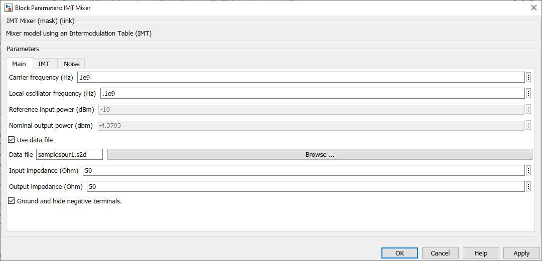
Consider the default data file samplespur1.s2d. This data file
contains IMT, AC, and noise data. When you specify the block to use this data file
by selecting the Use data
file parameter, the block extracts the reference input power,
nominal output power, IMT, and noise data from the data file. This image shows the
block mask with the extracted Reference input
power (dBm) and Nominal output
power (dbm) parameters.
To verify the extracted data, inspect the data file using this command
edit(samplespur1.s2d)

The block extracts the Nominal output power (dbm) from the data file using this equation.
This table shows you how the icons on this block will vary based on how you set the Simulate noise and Add LO phase noise parameters on the block.
| Simulate noise | Add LO phase noise: off | Add LO phase noise: on |
|---|---|---|
off |
| Not applicable. For more information, see Dependencies. |
on |
|
|


References
[1] https://www.mathworks.com/help/rf/examples/visualizing-mixer-spurs.html
[2] https://www.microwavejournal.com/articles/3430-the-use-of-intermodulation-tables-for-mixer-simulations
[3] Faria, Daniel., Lawrence Dunleavy, and Terje Svensen. "The Use of Intermodulation Tables for Mixer Simulations". Microwave Journal, April 2002. https://www.microwavejournal.com/articles/3430-the-use-of-intermodulation-tables-for-mixer-simulations.
[4] "RF Mixing / Multiplication: Frequency Mixers". Electronic Notes. https://www.electronics-notes.com/articles/radio/rf-mixer/rf-mixing-basics.php.