Output Custom Messages from IBIS-AMI Models
This example shows how to generate informational, warning, and error messages that can be output by a Tx or Rx IBIS-AMI Model executable during the initialization phase of simulation.
Background
In addition to passing numeric parameter values, passing text strings out of an IBIS-AMI model can be very helpful. These strings can be information messages about the model or simulation setup, warning messages about the configurations, or error messages that halt the simulation immediately. These messages can help with debugging potential problems or simply to verify that the setup is valid. Some example use cases are:
Validating that complex input parameter value combinations are correct and communicating any problematic combinations.
Validating that the AMI Init impulse responses input or output of the model are reasonable. When they are not, communicate why the responses are bad and how to fix them.
Testing that simulations conditions such as sample interval or symbol time meet model requirements and communicating when they do not.
Communicating additional detailed model information to the model user.
Note: Due to limitations in the IBIS-AMI Specification, message output is an Init-only feature.
Model Setup in SerDes Designer App
Adding messages does not require any specific Tx or Rx equalization blocks, so the first part of this example sets up some typical blocks using the SerDes Designer app. Launch the app with the following command:
serdesDesigner
Configuration Setup
Keep the default values in the Configuration panel:
Set the Symbol Time to
100ps(10GHz).Set the Modulation to
NRZ.Set the Signaling to
Differential.
Tx Model Setup
Add a FFE block to the Tx, keeping the default settings. Keep the default settings for the AnalogOut model as well.
Analog Channel Setup
Verify the Channel loss is set to 8 dB and the Differential impedance is set to 100 ohms.
Set the Target Frequency to
5GHz, which is the Nyquist frequency for 10 GHz.
Rx Model Setup
Keep the default settings for the AnalogIn model, then add a DFECDR block to the Rx. Keep the default settings for this block as well.
The final SerDes system should look like this:

Export SerDes System to Simulink
Save and then click on the Export button to export the configuration to Simulink®, where you will add Init Messages to the Tx and Rx blocks.
Model Setup in Simulink
The second part of this example takes the SerDes system exported by the SerDes Designer app and customizes it in Simulink.
Review Simulink Model Setup
This Simulink SerDes system contains the standard configuration: Stimulus, Configuration, Analog Channel, Tx, and Rx blocks, with all values carried over from the SerDes Designer app. Review each of these blocks to verify the setup is as expected.

Output Init Messages from Tx AMI Model
The following steps describe the process for adding messages to the Tx AMI Model.
Enable Init Messages in Tx Model
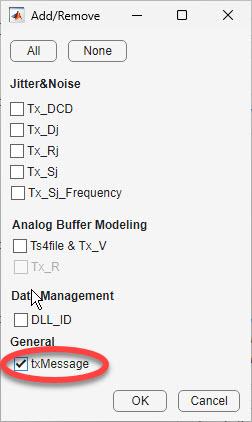
Open the IBIS-AMI Manager and select the AMI-Tx tab. Click on the Reserved Parameters button to bring up the Tx Add/Remove dialog. Select the txMessage checkbox and hit OK to enable the Init Messaging feature to the Tx AMI model.

A pop-up window opens to remind you to run Refresh Init since a new parameter has been added to the model. Select Refresh Init to add the new txMessage parameter to the Init function block.
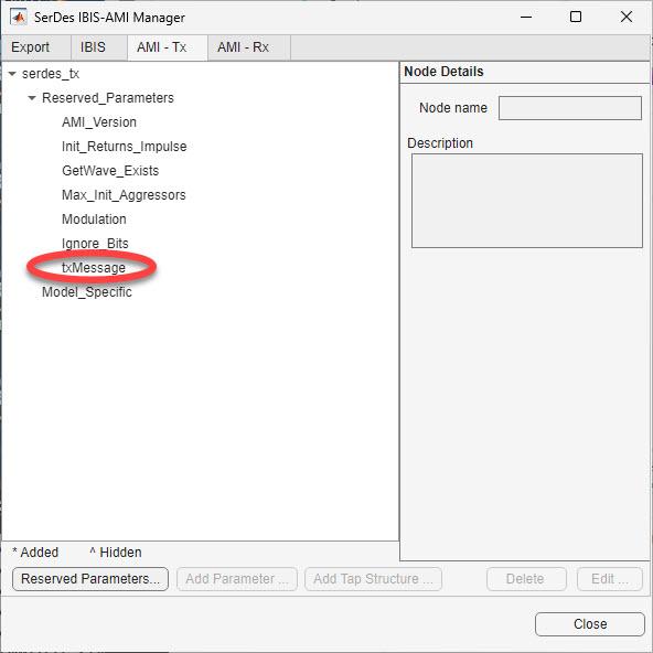
You will now see that txMessage has been added as a SerDes Toolbox Reserved Parameter in the Tx AMI tree.

Note that this parameter is not an actual IBIS-AMI Reserved Parameter. This parameter is only used by SerDes Toolbox for storing and Init Messages during code generation and will not be present in the AMI tree when the final AMI model executable is generated.
Add Init Messages to Tx Model
Highlight txMessage and select Edit… to bring up the txMessage dialog.
Select Add Message or Remove Message to add or remove as many messages as you would like to have. Add Message always adds to the bottom row. Remove Message removes the highlighted row. If no row is highlighted, the last row is removed.
From the Type drop-down, select
Info,Warning,orError. Info messages will be prepended with “**Info**”, Warning messages will be prepended with “**Warning**” and Error messages will be prepended with “**Error**”. Additionally, error messages will immediately terminate the simulation after the completion of Init.In the Message cell, enter your desired message, enclosed in double-quotes. Note the Index number (first column) for each message. This will be your index when selecting messages in Init in the next section.
Select OK when done.
The completed dialog should look similar to this:

Create Triggers for each Tx Init Message
Once you have created your list of desired messages, you now need to generate triggers for each message in the Tx Initialize function.
Look under the Tx subsystem and double-click on the Init block to bring up the mask. If you didn’t run Refresh Init when adding the txMessage parameter, you should do so now.
Click on Show Init to open the Tx Initialize MATLAB Function block. txMessage is now part of the function output:
function [ImpulseOut, txMessage] = impulseEqualization(ImpulseIn, RowSize, Aggressors, Modulation, SampleInterval, SymbolTime, FFEParameter)
Scroll down to the Custom user code area. The default value of txMessage has been added for you:
txMessage=0; % User added AMI parameter from SerDes IBIS-AMI Manager
This example shows you how to generate messages based on the currently selected value of Samples Per Bit (SPB).
When SPB is equal to 8, warning message 1 will be generated.
When SPB is equal to 16, warning message 2 will be generated.
When SPB is equal to 32, informational message 3 will be generated.
When SPB is greater than 32, error message 4 will be generated and then the simulation will be halted.
Inside the Custom user code area add the following code:
%% BEGIN: Custom user code area (retained when 'Refresh Init' button is pressed)
txMessage=0; % User added AMI parameter from SerDes IBIS-AMI Manager

spb = round(SymbolTime/SampleInterval);

if spb == 8
    txMessage = 1;
elseif spb == 16
    txMessage = 2;
elseif spb == 32
    txMessage = 3;
elseif spb > 32
    txMessage = 4;
end

 % END: Custom user code area (retained when 'Refresh Init' button is pressed)
Save, then run the model to check for errors. The model is now ready to generate IBIS-AMI Models.
Output Init Messages from Rx AMI Model
The process for using Init Messages in an Rx AMI Model is identical to the Tx Model. Instead of using the parameter txMessage, use rxMessage.
Using Init Messages in Simulink
As implemented above, Init messages are only visible when running the AMI DLL in an EDA tool such as Signal Integrity Toolbox; they are not visible when running in Simulink. To make these messages visible during Simulink simulations as well, you can use the MATLAB fprintf, warning and error functions.
To duplicate your messages in Simulink, first declare the error function as extrinsic so that it will be ignored during code generation, then duplicate each message using fprintf for Info messages, warning for warning messages and error for error messages as shown:
%% BEGIN: Custom user code area (retained when 'Refresh Init' button is pressed)
txMessage=0; %#ok<NASGU> % User added AMI parameter from SerDes IBIS-AMI Manager

% Make sure MATLAB error function is ignored in switch statement during codegen.
% Not required for warning since it will not halt the simulation.
coder.extrinsic("error");

spb = round(SymbolTime/SampleInterval);

switch spb
    case  8
        % Value for model executable
        txMessage = 1;
        % Value for Simulink simulations (Ignored during codegen)
        warning("Running at 8 Samples Per Bit. Recommend using 32.");
    case 16
        % Value for model executable
        txMessage = 2;
        % Value for Simulink simulations (Ignored during codegen)
        warning("Running at 16 Samples Per Bit. Recommend using 32.");
    case 32
        % Value for model executable
        txMessage = 3;
        % Value for Simulink simulations
        fprintf("Info: Running at 32 Samples Per Bit. Well done.");
    otherwise
        % Value for model executable
        txMessage = 4; %#ok<NASGU>  Message value is required in DLL executable.
        % Value for Simulink simulations (Ignored during codegen)
        error("Running at an unsupported Samples Per Bit.");
end

% Note: fprintf messages will also show up in STDOUT during EDA tool simulation.

% END: Custom user code area (retained when 'Refresh Init' button is pressed)
All these messages will be output to the Simulink Diagnostic Viewer and the error function will terminate the simulation just as it would when running the DLL in an EDA tool.
Generate IBIS-AMI Models
The final part of this example takes the customized Simulink model and generates IBIS-AMI compliant model executables, IBIS and AMI files for the Init message-enabled transmitter and receiver.
Export Models
Open the SerDes IBIS-AMI Manager and select the Export tab. On the Export tab:
Update the Tx model name to message_tx
Update the Rx model name to message
_rx.Note that the Tx and Rx corner percentage is set to
10. This will scale the min/max analog model corner values by +/-10%.Verify that Dual model is selected for both the Tx and Rx AMI Model Settings. This will create a model executable that supports both statistical (Init) and time domain (GetWave) analysis.
Set the Rx model Bits to ignore value to
1000to allow enough time for the external clock waveform to settle during time domain simulations.Set Models to export to
Both Tx and Rx.Set the IBIS file name to be message_models
.ibsPress the Export button to generate models in the Target directory.
Test Generated IBIS-AMI Model Executables
The Init Message capable IBIS-AMI models are now complete and ready to be tested in any industry standard AMI model simulator such as Signal Integrity Toolbox. You can test that each message is working correctly by running at 8, 16, 32, and 64 SPB.