Lane and Vehicle Detection in ROS Using YOLO v2 Deep Learning Algorithm
This example shows how to use deep convolutional neural networks inside a ROS-enabled Simulink® model to perform lane and vehicle detection. In this example, you first read traffic video as the input and publish the frames as sensor_msgs/Image messages to a topic on the ROS network. Then you detect vehicles, and the left and right lane boundaries corresponding to the ego vehicle in every frame, annotate the input image with the detections, and publish them to a topic in the ROS network. Finally, you generate CUDA® optimized code for the ROS node from the Simulink model for lane and vehicle detection.
This example uses the pretrained lane detection network from the Lane Detection Optimized with GPU Coder example of GPU Coder™. For more information, see Lane Detection Optimized with GPU Coder (GPU Coder).
This example also uses the pretrained vehicle detection network from the Object Detection Using YOLO v2 Deep Learning example of Computer Vision Toolbox™. For more information, see Object Detection Using YOLO v2 Deep Learning (Computer Vision Toolbox).
This example illustrates the following concepts:
Model the conversion of video frames to ROS image in Simulink.
Model the lane detection application in Simulink. First the traffic video is preprocessed by resizing to 227-by-227-by-3 and multiplying by a constant factor of 255. It is then fed to the pretrained network loaded in the
Predictblock from Deep Learning Toolbox™. Finally, if the left and right lane boundaries are detected, the parabolic coefficients to model the trajectories of the lane boundaries are obtained.Model the vehicle detection application in Simulink. The traffic video is processed by a pretrained YOLO v2 detector. This network detects vehicles in the video and outputs the coordinates of the bounding boxes for these vehicles and their confidence score.
Configure the Simulink model for CUDA ROS node generation on host platform.
Generate a CUDA executable for the Simulink model configured for ROS.
Third-Party Prerequisites
CUDA enabled NVIDIA® GPU
NVIDIA CUDA toolkit and driver
NVIDIA cuDNN library
Environment variables for the compilers and libraries. For more information, see Installing Prerequisite Products (GPU Coder) and Setting Up the Prerequisite Products (GPU Coder).
Overview
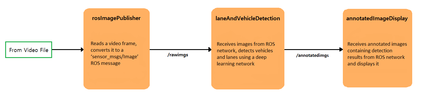
This example uses three Simulink models, which are each represented as ROS nodes. The following diagram illustrates their interaction. The rosImagePublisher node reads the raw video file and converts the frame data into a ROS image. The laneAndVechicleDetection node performs lane and vehicle detection and publishes the annotated image. The annotateImageDisplay node displays the annotated images as a video stream.
Download Example Video
if ~exist('./caltech_washington1.avi','file')
    url = 'https://www.mathworks.com/supportfiles/gpucoder/media/caltech_washington1.avi';
    websave('caltech_washington1.avi',url);
end
Get Pretrained Lane and Vehicle Detection Networks
The function downloads the trainedLaneNet.mat and yolov2ResNet50VehicleExample.mat files if they are not already present.
getVehicleDetectionAndLaneDetectionNetworks
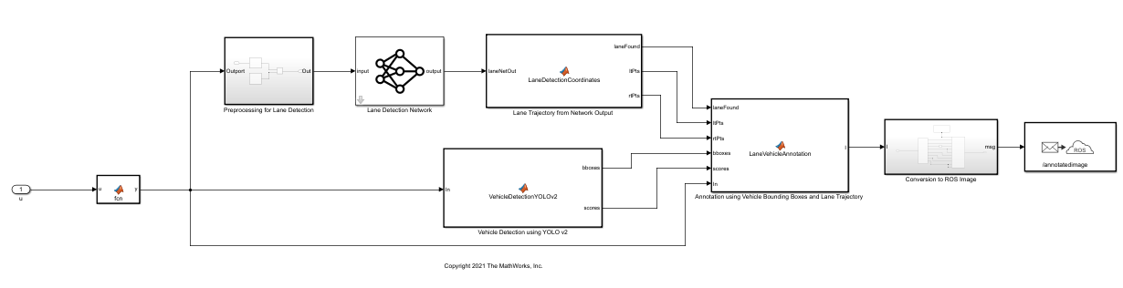
Lane and Vehicle Detection Simulink Model
The laneAndVehicleDetection model performs lane and vehicle detection as shown. When lane images are being published to the topic /rawlaneimgs, the model runs the detection algorithm on them and publishes the annotated images to a different topic. For a more detailed explanation of Lane Detection, Vehicle Detection or Annotation using Vehicle Bounding Boxes and Lane Trajectory subsystems, see Lane and Vehicle Detection in Simulink Using Deep Learning.
Run Simulation
Initialize the ROS master.
rosinit;
Open the Simulink models.
open_system('rosImagePublisher');
open_system('annotatedImageDisplay');
open_system('laneAndVehicleDetection');
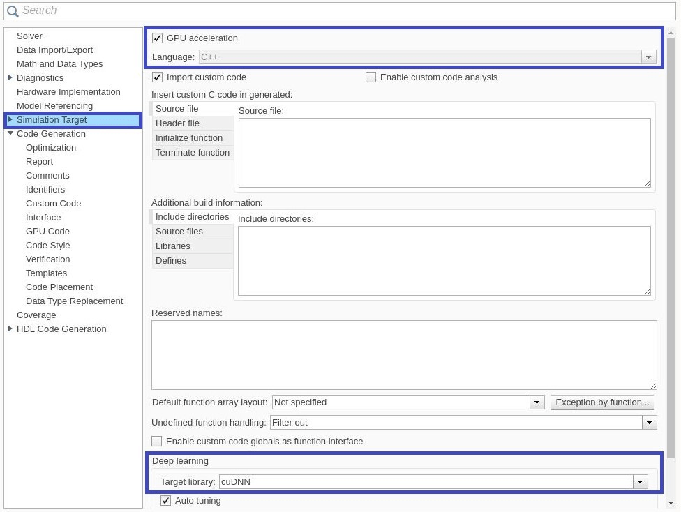
Open the Configuration Parameters dialog box of the laneAndVehicleDetection model. In the Simulation Target pane, select GPU acceleration. In the Deep Learning section, select the target library as cuDNN. Alternatively, you can set the parameters using the following commands.
set_param('laneAndVehicleDetection','GPUAcceleration','on');
set_param('laneAndVehicleDetection','SimDLTargetLibrary','cudnn');
set_param('laneAndVehicleDetection','DLTargetLibrary','cudnn');
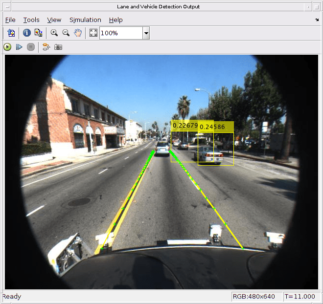
First run the models, laneAndVehicleDetection and annotatedImageDisplay, by selecting Run from the from Simulation tab. Then, run rosImagePublisher, which starts publishing video frames to ROS network. Every new frame received by annotatedImageDisplay is updated in the Video Viewer window.
Generate and Build Simulink Model
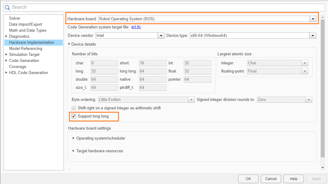
In the Hardware Implementation pane, select Robot Operating System (ROS) for Hardware Board and specify Device Vendor and Device Type.
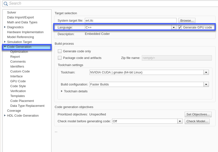
In the Code Generation pane, select the Language as C++ and enable Generate GPU code.
set_param('laneAndVehicleDetection','TargetLang','C++');
set_param('laneAndVehicleDetection','GenerateGPUCode','CUDA');
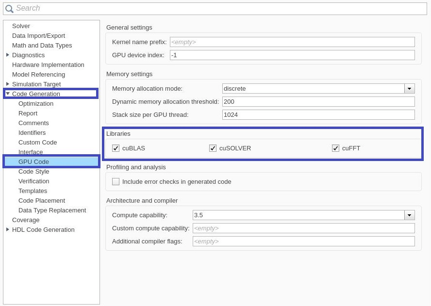
In the Code Generation > Libraries > GPU Code pane, enable cuBLAS, cuSOLVER and cuFFT.
set_param('laneAndVehicleDetection','GPUcuBLAS','on');
set_param('laneAndVehicleDetection','GPUcuSOLVER','on');
set_param('laneAndVehicleDetection','GPUcuFFT','on');
To configure ROS node deployment on your local host machine, in the Connect section of the ROS tab, set Deploy to Localhost. Click the Build and Run button from ROS tab to deploy the node. At the end of the build process, you will see the ROS node running on local host machine. Then, run annotatedImageDisplay model, you should be able to view the annotated image video in the Video Viewer output.
Related Topics
Lane Detection Optimized with GPU Coder (GPU Coder)
Object Detection Using YOLO v2 Deep Learning (Computer Vision Toolbox)